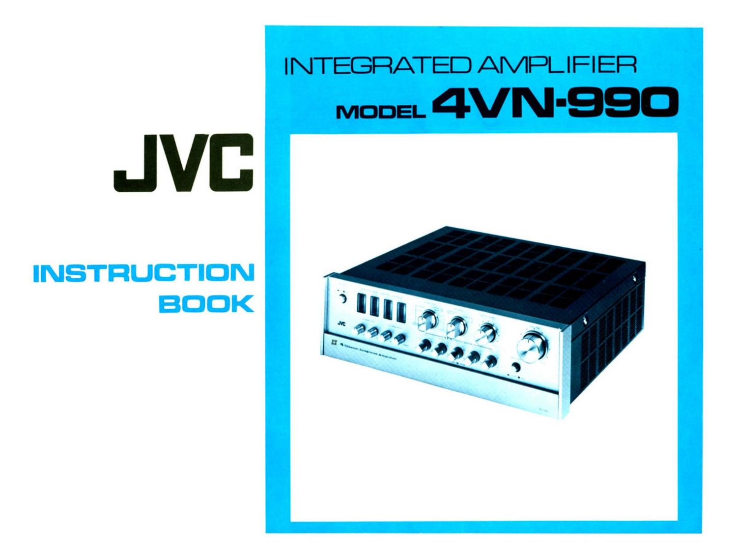
Jvc 4VN 990 Owners Manual

This is the 15 pages manual for Jvc 4VN 990 Owners Manual.
Read or download the pdf for free. If you want to contribute, please mail your pdfs to info@audioservicemanuals.com.

Page: 1 / 15
left right
Jvc 4VN 990 Owners Manual

Extracted text from Jvc 4VN 990 Owners Manual (Ocr-read)


Page 2

CAUHONS

This unit should be operated at the stated power. If the voltage exceeds
that stated by more than 10% it will damage the expensive components.
The 4VN-990 must be operated in conditions where ambient tempera-
ture is less than 95° F and relative humidity is less than 90%.

Heat will be generated if the 4VN-990 is used at more than 10 watts of
continuous power for more than 1 hour, so leave room for air to circu-
late in BTL 2-channel use.

Turn off the power before connecting any components as the click
noise could damage the speakers.

Connect the speaker and input terminals correctly as wrong polarity or
shorting will result in unstable sound or continuous activation of a
protective circuit. A poor ground contact may result in hum which may
damage the speakers.

After turning the power switch ON or OFF wait for 7 or 8 seconds
before adjusting the controls to avoid impact noise.

Use speakers with an impedance of 4a or higher. If the impedance is
lower than 49 the protective circuit will be activated and the sound
will be intermittent.

When the speaker sound is intermittent or ceases because of the acti-
vation of a protective circuit. turn off the power and investigate.

Never touch any of the mechanical or electronic parts inside the cabinet.
0 The capacity of the power cord is 500 watts. The total power supplied
from the AC outlets of the MIN-990 to external equipment should be
less than 300 watts.

When the power switch is turned ON and OFF repeatedly speaker sound
may be interrupted. This is normal and is not due to any defect.

Take care with the AC plug. Do not bend the cord perpendicularly to
the plug, grasp the plug when pulling it from the AC outlet and dont
apply any force to the cord.

CONTENTS

Cautions ....................................... 1
Connection Diagram .............................. 2
Rear Panel Connections ............................ 3
Front Panel Controls (Upper) ....................... 4
Front Panel Controls (Lower) ....................... 5
Operation Chart ................................. 6
Speaker Connections .............................. 7
Operation - Discrete 4-Channel ..................... 7
Operation - 2-Channel ............................ 7
S.E.A. ......................................... 8
S.F.C.S. ....................................... 9
Level Control ................................... 10
Low Cut/High Cut Filters .......................... 10
Loudness Controls ............................... 10
B.T.L. Connection ............................... 10
Supplementary Information ........................ 10
Performance Graphs .............................. 11
Block Diagrams .................................. 12
Specifications ................................... 13
Troubleshooting Chart ............................ 14