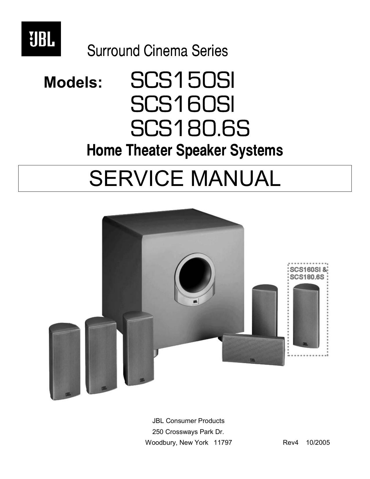
JBL SCS1 50SI SCS1 60SI SCS1 80 6S Owners Manual
This is the 27 pages manual for JBL SCS1 50SI SCS1 60SI SCS1 80 6S Owners Manual.
Read or download the pdf for free. If you want to contribute, please upload pdfs to audioservicemanuals.wetransfer.com.
Page: 1 / 27