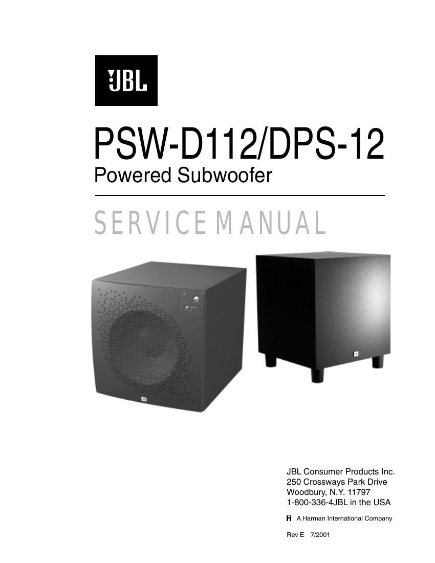
Jbl dps 12 service manual

This is the 35 pages manual for jbl dps 12 service manual.
Read or download the pdf for free. If you want to contribute, please mail your pdfs to info@audioservicemanuals.com.

Page: 1 / 35
left right
jbl dps 12 service manual

Extracted text from jbl dps 12 service manual (Ocr-read)


Page 1

SAFETY INFORMATION Warning Caution Leakage/Resistance Check List of Safety Components Requiring Exact Replacements (all parts POWER AMP PCB except TR2) C6 (Rev0 ) 4.7uf 100V 80/-20% Electrolytic redial NP C6 (Rev1 ) 4.7uf 100V 80/-20% Electrolytic redial NP TR2 MPS A13 30V NPN(Darl) R4a/b/c 0.1 0.5W 5% metal film R9 3.3 5W 5% ceramic wirewound R15 100k 0.5W 5% carbon film DBR Bridge Rect 200V Use only factory replacement. R1 10M 0.25W 5% carbon film R16, 17 1.8k 5W 5% ceramic wirewound R33 (Rev0) only) 332 0.5W 5% carbon film R50 (Rev0) only) 332 0.5W 5% carbon film R52, 57 2.7k 5W 5% ceramic wirewound R61 3.9k 3W 5% carbon film S64AMI Power output module. Use only factory replacement Faceplate Faceplate. Use only factory replacement CMC1 Use only factory replacement L1 Use only factory replacement Fuse PCB Use only factory replacement Main PCB Use only factory replacement 4700uF,50V electrolytic filter caps. Be sure replacement part is at least the same working voltage and capacitance rating. Also the lead spacing is important. Incorrect spacing may cause premature failure due to internal cabinet pressure and vibration. 2 Amplifier/Subwoofer PSW-D110/DPS-10 F1 PWRCORD TRX1 C1, 2 Transformer. Use only factory replacement. SPT-2 or better with polarized plug, UL approved wire with the hot side to fused side. Use with factory replacement panel strain relief only. Fuse SLO BLO 1.25A 250V UL approved Any p ers o n p erfo rm in g s e rv ic e o f t h is u nit w ill b e e xp ose d t o h a za rd o us v o lt a ge s a n d t h e r is k o f e le ctr ic s h o ck. I t is a ssu m ed t h at a ny p ers o n w ho r e m ove s t h e a m plif ie r f r o m t h is c a bin et h as b een p ro perly t r a in ed in p ro te ctin g a gain st a vo id able i n ju ry a nd s h ock . T here fo re , a ny s e rv ic e p ro ce dure s a re t o b e p erfo rm ed b y q ualif ie d s e rv ic e p ers o nal O NLY ! B efo re r e tu rn in g t h e u n it t o t h e c u sto m er, p erfo rm a l e aka ge o r r e sis ta nce te st a s fo llo w s: L e aka g e C urre nt. N ote t h ere is n o p o w er s w it c h o n t h is u nit . W hen t h e p ow er p lu g is p lu gged in , t h e u nit is liv e . C onnect t h e u nit t o i t s r a te d p ow er s o urc e . U sin g a n a m mete r, m easu re t h e c u rr e nt b e tw een t h e n e utr a l s id e o f t h e A C s u pp ly a nd c h a ssis g ro u nd o f t h e u nit u nd er t e st. I f l e aka g e c u rre n t e xce e ds 0 .5 A , t h e u nit i s d e fe ctiv e . R eve rs e th e p ola rit y o f th e A C s u pply a nd r e peat. R esis ta nce . M easu re t h e r e sis ta nce f r o m e it h er s id e o f t h e l in e c o rd t o c h a ssis g ro und. I f it is le ss t h an 5 00k o hm s, t h e u nit is d efe ctiv e . W ARNIN G ! D O N O T r e tu rn t h e u nit t o t h e c u sto m er if it f a ils o ne o f t h ese t e sts u ntil t h e p ro ble m is lo ca te d a nd c o rre cte d. T h is u n it d oes n ot h ave a p o w er s w it c h . H aza rd o us v o lt a g es a re p re se n t w it h in t h e u n it w hen eve r i t i s p lu gged in . B efo re t h e a m pli f ie r is p lu gg ed in , b e s u re it s r a te d v o lt a ge c o rre sp o nds t o t h e v o lt a ge o f t h e A C p ow er s o urc e t o b e u se d. I n co rre ct v o lt a ge c o uld c a use d am age t o t h e a m plif ie r w hen t h e A C p ow er c o rd is p lu gged in . D o n ot e xce e d r a te d v o lt a ge b y m ore t h an 1 0% : o pera tio n b e lo w 9 0% o f r a te d v o lt a ge w ill c a use p oor p erfo rm ance o r m ay s h ut th e u nit o ff. 0 0465-2 IM PO RTA NT S ER VIC E N O TE S: W hen t e stin g t h e P SW -D 11 2/D PS -1 2 S erie s a m plif ie r, a l o ad m ust a lw ays b e co nnecte d t o t h e o utp ut t e rm in als , w heth er t h e w oofe r, o r a 4 t o 8 o hm r e sis tiv e l o ad . A ll A C p ow ere d t e st in str u m en ts ( m ete rs , o scillo sco pes, e tc .) m ust h ave a f lo atin g g ro und , i. e ., b e co nnecte d t o a n is o la tio n t r a n sfo rm er. Critical Components All components identified with the IEC symbol in the par ts list and the schematic diag ram designate components in which saf ety can be of special significance when replacing a component identified with . Use only the replacement parts designated in the par ts list or parts with the same r ating of resistance , wattage or v oltage.

Page 2

3 Amplifier/Subwoofer PSW-D112/DPS-12 TABLE OF CONTENTS SAFETY INFORMATION .......................................................2 TABLE OF CONTENTS .........................................................3 GENERAL SPECIFICATIONS ...............................................3 DETAILED SPECIFICATIONS ...............................................4 CONTROLS AND THEIR FUNCTION ...................................6 OPERATION...............................................................\ ............7 SPEAKER CONNECTIONS ...................................................8 TROUBLESHOOTING .........................................................10 TEST SET UP AND PROCEDURE ......................................11 TESTING PROCEDURE ......................................................12 POWER AMP MODULE TESTING FLOW CHART ............14 SERVICE BULLETIN JBL2001-02 - FEBRUARY 2001........16 SERVICE BULLETIN JBL9903 Rev 1 - FEBRUARY 200 1 ..15 CABINET EXPLODED VIEWS ............................................17 AMPLIFIER EXPLODED VIEW ...........................................18 MECHANICAL PARTS LIST ................................................19 PACKING EXPLODED VIEWS ....................................20 Rev0 PCB (Component Side) ......................................21 Rev0 PCB (Solder Side) ..............................................22 PCB (Component Side) PREAMP Rev1, PWRAMP Rev1 ............................................................23 PCB (Solder Side) PREAMP Rev1, PWRAMP Rev1 ............................................................24 ELECTRICAL PARTS LIST (Rev0) .............................25 ELECTRICAL PARTS LIST Rev1 PCB .......................27 INTEGRATED CIRCUITS ............................................29 SCHEMATIC 1of3(Rev0) .........................................30 SCHEMATIC 2of3(Rev0) .........................................31 SCHEMATIC 3of3(Rev0) .........................................32 PREAMP SCHEMATIC Rev1 ......................................33 POWERAMP SCHEMATIC Rev1.0 .............................34 POWERAMP SCHEMATIC Rev1.1 .............................35 GENERAL SPECIFICATIONS Amplifier Power (RMS) ........2 50watts Driver 12" ............. High-Polymer Laminate Inputs ............... Line Level and Speaker Level Outputs .............. Line Level and Speaker Level Low-Pass Frequency ........ Continuously variable from 60Hz -“180Hz High-Pass Frequency ........ Continuously variable from 60Hz -“180Hz when using line-level inputs 150Hz when using speaker-level inputs Frequency Response ........ 28Hz -“low-pass crossover setting PSW-D112 DPS-12 Dimensions (HxWxD )....... 17-1/2 x17-1/2 x19-1/8" 22-1/8 x17-1/2 x17-1/2" (445 x445 x486mm) (562 x445 x445mm) Weight ...............4 0lbs/18.2 kg 38 lbs/17.3kg NOTE: CERTAIN DRAWINGS AND CONNECTIONS WERE DEPICTED INCORRECTLY IN SOME EARLY COPIES OF THE PSW-D112 AND DPS-12 OWNER'S MANUALS . THEY INCLUDE: 1.DRAWING OF RCA LINE LEVEL INPUT/OUTPUT JACKS ON PAGES 3, 4, &5;ALL CHANNELS -RIGHT SIDE SHOULD BE LINE OUT, LEFT SIDE SHOULD BE LINE IN. 2.CONNECTION ON PAGE 4OFOWNER'S MANUAL -SINGLE CABLE DIRECT INPUT (FOR DOLBY DIGITAL OR DTS SURROUND); SINGLE CABLE FROM YOUR RECEIVER/PROCESSOR SHOULD CONNECT TO: Rev0 version -THE CENTER CHANNEL LINE IN JACK ON YOUR SUBWOOFER. Rev1 version -EITHER LEFT OR RIGHT INPUT JACK ON YOUR SUBWOOFER. THOSE DRAWINGS ARE CORRECT IN THIS DOCUMENT, SEE PAGES 8 & 9.