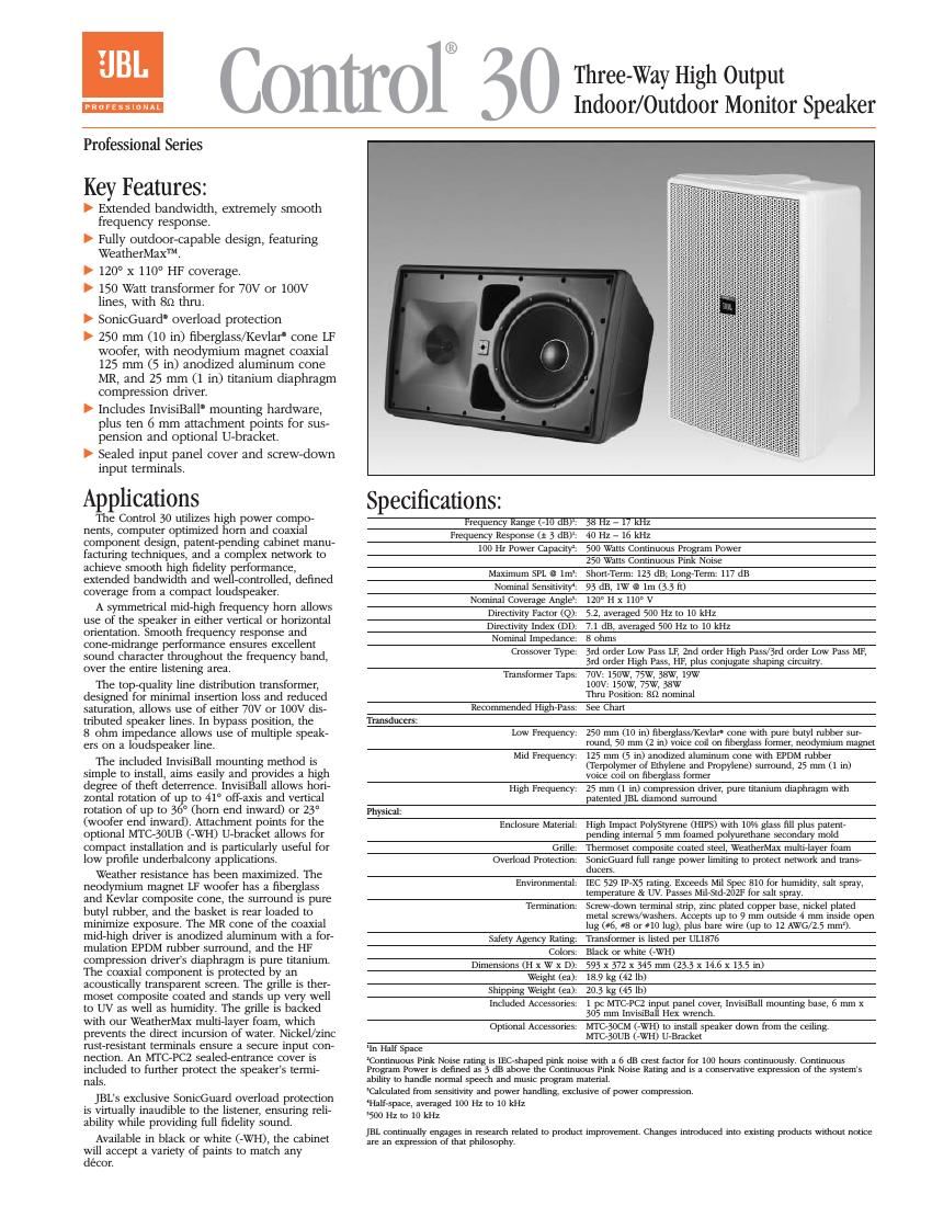
Jbl control 30 owners manual

This is the 4 pages manual for jbl control 30 owners manual.
Read or download the pdf for free. If you want to contribute, please mail your pdfs to info@audioservicemanuals.com.

Page: 1 / 4
left right
jbl control 30 owners manual

Extracted text from jbl control 30 owners manual (Ocr-read)


Page 1

Control 30 Three-Way High Output Indoor/Outdoor Monitor Speaker 100 1000 10000 SPL, 2.8V,1m (dB) 60 70 80 90 100 Impedance (Ohms) 1 10 100 Frequency (Hz)316 20000 20 46 [1.8] 100 [3.9] 84 [3.3] 115 [4.5] 130 [5.1] 12 C/ L 345 [13.5] 556 [21.9] C/ L 110 [4.3]127 [5.0]107 [4.2] 237 [9.3] 211 [8.3] 128 [5.0] 109 [4.29] 87 [3.42] 106 [4.17] 593 [23.3] 372 [14.6] Dimensions in mm [inches] 7.2 [0.28] x 4 100 1000 10000 Attenuation (dB) -30 -20 -100 10 0 deg Horz 10 deg Horz 20 deg Horz 30 deg Horz 40 deg Horz 50 deg Horz Frequency (Hz) aed Oas 2020000 100 1000 10000 Attenuation (dB) -30 -20 -100 10 0 deg 10 deg up 20 deg up 30 deg up 40 deg up 50 deg up Frequency (Hz) oaedeUpOas 20 20000 100 1000 10000 Attenuation (dB) -30 -20 -100 10 0 deg 10 deg down 20 deg down 30 deg down 40 deg down 50 deg down Frequency (Hz) 2020000 Frequency Response, on axis in half-space (2,dotted line) and full space (4,solid line) at thru (8 -„¦) setting, Input Impedance. 100 1000 10000 -6dB Beamwidth (degrees) 10 100 V Beamwidth H Beamwidth Frequency (Hz) 360 2020000 Beamwidth vs. Frequency Horizontal Off Axis Frequency Response 100 1000 10000 0 10 20 Directivity Factor (Q) 1 10 100 Frequency (Hz) Directivity Index (dB) Directivity Index (DI) ,dB 20 20000 Directivity Index, Q Vertical Off Axis Frequency Response (up) Vertical Off Axis Frequency Response (down)

Page 2

Horizontal 1/3 Octave Polars Architectural Speciļ¬cations: The loudspeaker shall consist of a 250 mm (10 in) low frequency transducer, a coaxial 125 mm (5 in) mid frequency transducer with a 25 mm (1 in) compression driver, and frequency dividing network. The low frequency drivers voice coil shall be 50 mm (2 in) in diameter and the mid frequency drivers voice coil shall be 25 mm (1 in) in diameter. Performance speciļ¬cations of a typical unit shall be as follows: Usable frequency response shall extend from 38 Hz to 17 kHz (10 dB below rated sensitivity, half-space, no external equalization). Rated power shall be at least 500 watts continuous program power for 100 continuous hours duration (deļ¬ned as 3 dB above a test signal of ļ¬l- tered random pink noise conforming to IEC268-5). Measured sensitivity shall be at least 93 dB-SPL (at 1m [3.3 ft] with 2.83V input, avg. 100 Hz to 10 kHz). The input shall be switchable for use either at nominal 8 ohms, or on a 70.7V or 100V distributed speaker line via built-in transformer. Selectable taps shall nominally be 150W, 75W, or 38W on a 70.7V or 100V distributed line, plus 19W on 70.7V line only. The system shall be protected against damage from occasional over- powering via full range limiting, which shall be inaudible during activation. The coaxial mid-high driver shall be horn loaded to cover 120 degrees horizontal by 110 degrees vertical with a high degree of accuracy. The cabinet shall be molded High Impact PolyStyrene (HIPS) with ten percent glass ļ¬ll, and a 5 mm internal foamed polyurethane secondary mold. The grille shall be backed by multi-layer foam and be secured via screws to keep it in place when facing downward. The cabinet and grille shall be paintable. The low frequency transducer shall have a neodymium magnet, a cone of woven ļ¬berglass and Kevlar Ā®and butyl rubber surround, with the frame protected from direct weather exposure. The mid frequency transducer element of the coaxial mid-high driver shall have an anodized aluminum cone with an EPDM rubber (a Terpolymer of Ethylene and Propylene) surround, with the frame protected from direct weather exposure. The compression driver shall be constructed with a titanium diaphragm for weather resistance. The coaxial mid-high driver shall be protected with a secondary acoustically transparent screen. The system shall withstand Mil Spec 810 testing with speciļ¬ed durations with no effect on its acoustical performance or structural integrity; salt spray (method 509.3), temperature (method 501.3 and 502.3), humidity (method 507.3) and ultraviolet (method 505.3). Further, it shall pass Mil-Std-202F (method 101D) for salt spray. They system shall have an IEC 529 splashproof rating of IP-X5. For theft deterrence, the installation access area shall be hidden behind a snap-out cover on the front grille. The included ball mecha- nism shall be internal to the cabinet. The cabinet shall have ten (10) 6mm mounting points including 3 on each side and 3 on top and bottom and an accessory U-bracket shall be available. The grille logo shall be rotatable for proper orientation with loudspeaker mounted horizontally or vertically. The external wiring connectors shall be screw-down terminals. Overall cabinet dimensions shall be no greater than 593 high x 372 mm wide x 345 mm deep (23.3 x 14.6 x 13.5 in) and shall weigh no more than 18.9 kg (42 lb). The ļ¬nish shall be lightly textured black or white. The system shall be the JBL Model Control 30 (or Control 30-WH) with included InvisiBall Ā®(mounting system).