Jbl 2426 h brochure

This is the 2 pages manual for jbl 2426 h brochure.
Read or download the pdf for free. If you want to contribute, please mail your pdfs to info@audioservicemanuals.com.

Page: 1 / 2
left right
jbl 2426 h brochure

Extracted text from jbl 2426 h brochure (Ocr-read)


Page 1

{IBL

Compression Driver

Professional Series

Key Features:
25 mm (1 in) horn throat diameter
>Alternate 1 3/8

>70 watts continuous program at
800 Hz

D100 watts continuous program
above 1.2 kHz

44 mm (1% in) pure titanium
diaphragm

- 18 screw mounting

D Patented diamond-pattern
diaphragm suspension

44 mm (13/4 in) edgewound
aluminum ribbon wire voice coil

DCopper-plated pole piece for
reduced inductance and increased
high-frequency output

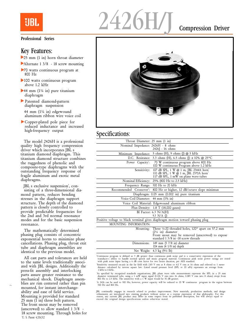
The model 2426H is a professional
quality high frequency compression
driver which incorporates JBL s
titanium diamond diaphragm. This
titanium diamond structure combines
the ruggedness of phenolic and
composite- ty e diaphragms with the
outstanding requency response of
fragile aluminum and exotic metal
diaphragms.

JBL s exclusive sus ension, con-

sisting of a three- 'mensional dia-
mond pattern, reduces bending
stresses in the diaphragm support
structure. The depth of the diamond
pattern is closely controlled to
provide predictable frequencies for
the 2nd and 3rd normal resonance
modes and for the basic suspension
resonance.

The mathematically determined
phasing plug consists of concentric
exponential horns to minimize phase
cancellations Phasing plug, throat exit
tube and diaphragm assemblies are
identical to the previous model.

All cast parts and tolerances are held
to the same levels traditionally associ-
ated with JBL designs. Additionally the
press-fit assembly and interlockin
parts assure greater res1stance to t e
mechanical shock. Diaphragm assem-
blies are rim centered rather than pin
mounted, for instant interchange-
ability arid ease of field serv1ce
Mounting 1s provided for standard
25 mm (1 in) three bolt pattern.

The front snout may be removed
(unscrewed) to allow standard 1 3/8 -
18 screw mounting. Through holes for
U. 5. Patent 4,324,312

Specifications:

Throat Diameter: 25 mm (1 in)

Nominal Impedance: 2426H - 8 ohms
2426] - 16 ohms

Minimum Impedance: 5 ohms (H), 9 ohms (I) @ 5 kHz

D.C. Resistance: 3. 3 ohms (H) 6.5 ohms (I) + 10% @ 25°C

70 W continuous rogram above 800 Hz

Power Capacity:
100 W continuous rogram above 1. 2 kHz

Sensitivity: 107 dB SPL, 1 W @ 1 m, JBL 2344A horn
110 dB SPL, 1 W @ 1 m, JBL 2370A horn'
117 dB SPL, 1 mW on plane wave tubes

Nominal Efficiency: 25% (800 Hz to 2.5 kHz)

Frequency Range: 500 Hz to 20 kHz

Recommended Crossover: 800 Hz or higher, 12 dB/octave slope minimun

Diaphragm: 0.05 mm (0.002 in) pure titanium

Voice Coil Diameter: 44 mm (1% in)

Voice Coil Material: Edgewound aluminum ribbon
Flux Density: 1.8 T (18,000 gauss)

Bl Factor: 6.3 N/A(H)
9.3 N/A 0)

Positive voltage to black terminal gives diaphragm motion toward phasing plug

MOUNTING INFORMATION:

Mounting. Three /1- 20 threaded holes, 120° apart on 57.2 mm
(2% in) diameter
Front snout may be removed (unscrewed) to expose
standard 1 3/8 in- -18 screw threads

Dimensions: 149 mm (5 7/8 in) diameter

104 mm (4 1/8 in) depth

Net Weight: 4.3 kg (9V2 lb)

(1011111111111; 1111111111. 11 1111111111 11 3 1113 1111111 111111 101111111111111 1111111 1111111 11111 11 1 11111111111111 11111111111111 of 1111
111111111111 11111 1 11 111111111 1111111111 11111111 11111 111111 1111111111 1111111111 0111111111011 1111111 1111111 11111111 11111111 111 1111111
1111111 1111111 1111111 11111111 11111111; 1 1. as 11111 1111111 1111 11111 1111111 111111111111, pet AES 11111111111

5111111111111 1111111111 011111111 111 1111 111 111111 111111 2.33 v 11111 11 8 0111111 111 4.0 v 11111 11 111 11111111 1111 111111111 10 1 1111111
1111111111 11111111111 by 11111111 11111111 11111. 1111111 11111111 1111111111 11111 ($121. 11 20 11:1) 1111111111; 111 11111111 1111111
1k; to 4 kHz.

A1 51111111111 by 111011111111 111111111111 0111111211115» 131. 1111111 111111 111111 11.111111111111111 1111111111 1111 511 111 1 25 111111
1111111111 1111111111111 111111. 1151111 1 1 111w 11111111 signal (c.1211 v 11111 111111 16 11111111. 0.019 V 11111 111111 3 11111111) 1111111 (mm
m 111 111 2.5 1111:, T11 1111111111111 1111111 1 1 w 11111111 would 111 so 111; 1111111

A 24211 1111 111 111111 111 soc 11;, 1111111111, 111111111 1111111111 W111 11 1111111111 11 23 w 1111111111111 1111111111 111 1111 11111111 111111111
500 Hz and 800 Hz.

1131. 11111111111111 11111311 111 11111111 11111111 10 1111111111 1.1111111111111111. N111 1111111111 111111111111 111111111111 1111 111111111
1111111111111 111 1111111111111 1111 1111111113 11111111111 w111111111 1101111 11 1 1111111111 1111111111111 of 11111 11111010111111 F111 11111
11111111, .1111 111111111 1111. 1111111111 11111 1111111 111 1111111 11111111 111111 11.1 11111111111111 111111111111 11111 11111 11111111 1111111 111
1111111 1111 1111111111 1111111 11111111111101: 11111111 1111111111111 1111111

Page 2

V 2426H/J Compression Driver

external attachment points are also provided. A machined Response on JBL 2370 Flat-Front Bi-RadialiHorn
ring of copper surrounds the pole piece to counteract the

Impedance Ohms

. . . . . 120
inductance of the votce c011 at high frequencies. After
manufacture, the frequency response of each driver is
tested for conformity to rigid performance standards.
The 2426H is offered in an 8 ohm impedance, and A:
the otherwise identical 2426] is offered in a 16 ohm 2 ma
. o
impedance. b
m
u
.l
. . . . a
. tn
Architectural Spec1f1catlons. w
The compression driver shall consist of a ferrite magnetic structure.
All magnetic assembly parts shall be machined from cast or extruded so ' _
billet stock. The phasing plug shall be assembled of concentric horns W 1000 WOW 290
to minimize phase cancellations, and it shall be further coupled to a qunemy Z
tapered throat. Driver mounting shall consist of a removable snout _
incorporating standard 25mm (1 in) three bolt pattern and fitted with Frequency resinome of the 24_2-JH coupled to a JBL 2370_Flat-Front Bt-
three external attachment points. The snout shall be removable to Radial horn, measured on-axis at a distance of 1 meter with a 1 wan
allow the use of 1 3/8" . 18 screw-thread attachment. (2.83 V RMS) input in a reflection-free environment, with impedance
The diaphragm shall be 0.05 mm (0.002 in) pure titanium pneumat- VS- frequency curve. The increased high-frequency. Output is due to
ically drawn to shape. High frequency response shall be controlled the horn desrgn S increasmg directivity 1n the vertical plan.

through the use of a three-dimensional suspension structure. The
voice coil shall be edgewound aluminum ribbon of not less than 44
mm (1% in) in diameter, operatin in a magnetic field of not less than Response on Plane-Wave Terminated Tube
1.8 tesla (18,000 gauss). An impe ance controlling ring shall be affixed
to the pole piece in order to increase efficiency at high frequencies. 1)!
Performance s ecifications of a typical production unit shall be as 5
follows: MeasuredI sensitivity with a l m W input on a 25 mm (1 in) ter-
minated tube, averaged from 800 Hz to 2.5 kHz, shall be at least 117 uv
dB SPL. Measured sensitivity with a 1 \X/ input at 1 in distance on-axis
from the mouth of a horn with a Q of 6.3, averaged in the 2 kHz octave
band, shall be at least 110 dB SPL. As an indication of electromechani-
cal conversion efficiency, the Bl factor shall be at least 6.3 (9.3) new-
tons per ampere. Frequency response, measured on a terminated

spt an be 2m. paw

imp-dance onms

tube, shall be flat within 2 1 dB from 800 Hz to 3.3 kHz, with a 6 dB/ an
octave rolloff above that point. Nominal impedance shall be 8 [16]
ohms and power capacity shall be at least 70 watts normal speech or
music program material. mm,
The compression driver shall be JBL Model 2426 H D]. Other _
drivers will be considered for equivalenc provided that submitted Frequenty response and-impedance modulus 0f MOdEI 24261-1
data from a recognized independent test laboratory verify that the COQPIFd l0 3 25 mm (1 In) diameter terminated plane-wave tube.
above performance specifications are met. This is the power response of the transducer, and is the frequent)

response that will be obtained on a true full-bandwidth constant-
directivity horn design, such as JBL s 2360 series of Constant
Coverage Bi-Radial'Horns.

104
(4-3/32)

25.6 23
m D|A 3.5 in (15/15;
2 (9132):!PL 01/32)
W 36.5
(ta/ts)
. se


134
(59/32!

114-20 UNC-zB

g $231M t-a/a x15 UNEF-B

NDIE: DIMENSIONS IN 1 J

ARE lN INCHES. I] B L
o

JBL Professional
8500 Balboa Boulevard, PO. Box 2200

Nonhridge, California 91329 USA. $33223,"
H A Harman International Company Fl055