Itt Weekend 80

This is the 8 pages manual for itt Weekend 80.
Read or download the pdf for free. If you want to contribute, please mail your pdfs to info@audioservicemanuals.com.

Page: 1 / 8
left right
itt Weekend 80

Extracted text from itt Weekend 80 (Ocr-read)


Page 1

ySCHAUB-WBENZ

,,WEEKEND 80 Automulik"

Typ 120161 welnrot wine red
Typ 120163 royalblau royal blue
Typ 120167 perlweifl pearl white
Typ 120169 anihrazit anthracite

1967

S'fifiim

2me

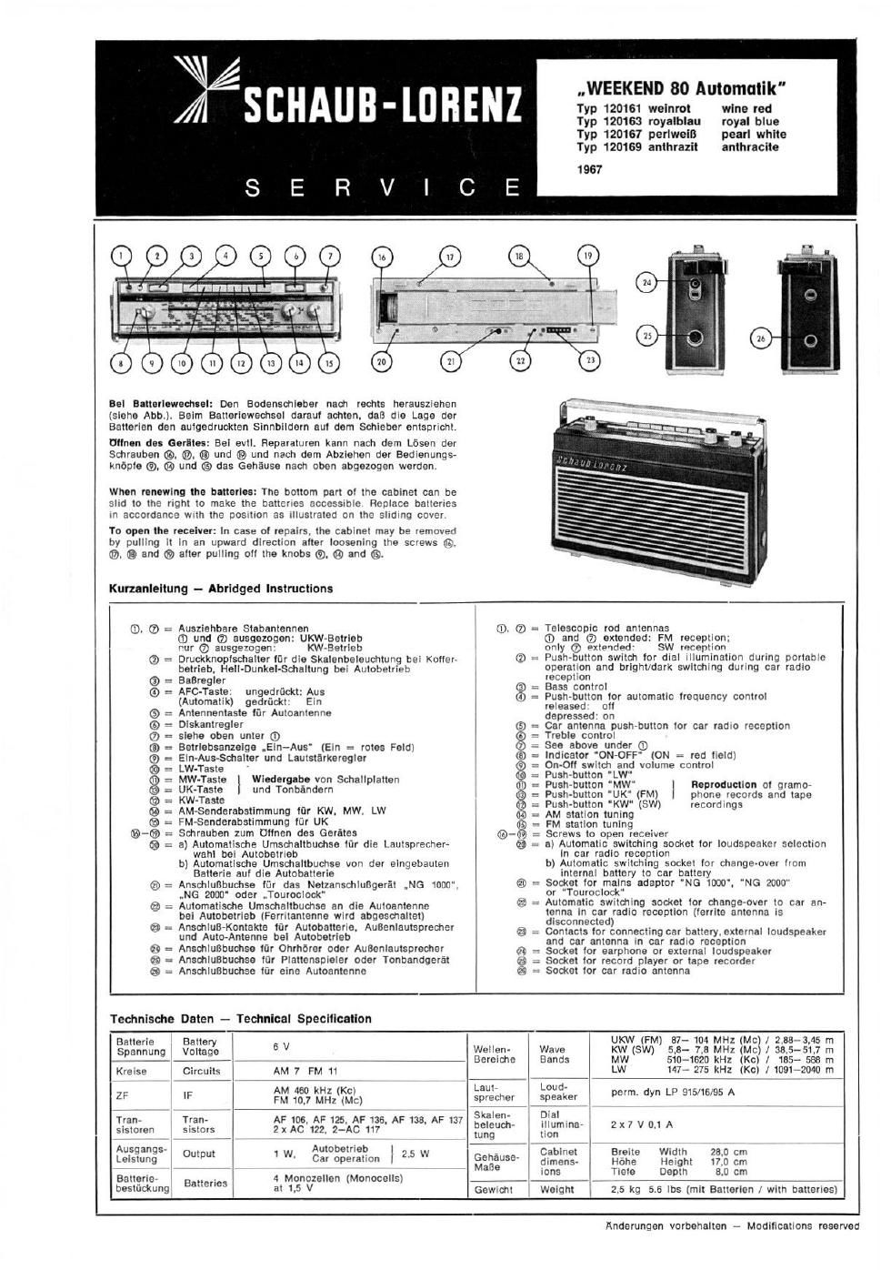
Hal Bltlarlcwedtul: Den Bodensdlllber nach rechts herausziehen
isiehe Abbi Balm Batterieweuhsal daraul aehien. doll die Logo der
Batterien den aulgedruckten Sinnbildern aul dam Schieber entspricht

Ulln-n do: Gerltu: Bel evii. Reparaturen kann naoh darn Lésen der
Schrauben @. @, ® und ® und nach dem Abzrenen der Bedtenungs-
knbple ®, ® um! 03 Gas Gehéuse nach oben abgezogen werden

When Ion-wing In blllorles: The bottom par! oi the cabinet can be
slid to [he rtgitl IO make the batteries flCCCSSIbIC Replace ballerres
m accordance wrth the oosrtton as illustrated on the sitdtnq cover

To op." the receiver: In case 01 repairs the cabinet may be removen
by pulling it in an upward direction alter loosening the screws S?
®, ® and ® alter pulling all the knobs ®, ® and (9

Kurzanlellung - Abridged Instructions

9
6)

: Ausziehbare Stabantennen
® und ® ausgazogen: UKW-Betriob
rm (7') ausgemgen' KW Battier:
n Drudtknoplschaiter itir die Skalenbeleuwiung tei Kuiier»
betrlob. Heli-DunkeI-Sehaitung bei Autobetrteb
Eaeregier
AFC-Taste: ungedrttcktrAus
(Automalik) QGdrfickl: Eln
: Antennentaste ltir Autoanienne
Diskanlregler
siehe Oben unler ®
Betriebsanzeigo .Ein-Aus' (Ein :- rotes Feidi
Ein»Aus-Sdtalter und Lautstarkeregler
LW-Tasle
MW-Taste
UK-Taste
KW~Tasie
AM-Senderabstimmung lt'ir KW. MW, LW
FM-Senderabstimmung liir UK
Schrauben zum Uiinon des Gerétos
a) Automfllische Umschaitbuehsa lflr die Lautsptecher-
wahl bei Auiohetrteb
b) Automatische Urnschaitbuchse von der eingcbauten
Balterie aul die Autobatterie
Anschlulibuchsa liir das Netzansdtiungarét
.N6 2000' oder uTouroclock

Winery-be von Schaiipiatten
und Tonbéndarn

®
séeeemeeeszae ea @

.,NG 1000.

a -- Automatisdte Umsohaltbuchse an die Auioantenne
bei Aulobetrieh (Ferrttantenne wird abgeschaliet)
63 : AnsdtluB-Koniakta l0! Autobatterie. Auflenlauisprecher

und Auto-Antenna bal Autobeirieb
Ansehluflbuchse lfir Ohrhérar oder Auflcnlautsprecher

= Bass control
7 Pustt~button tor automatic irequency controi

, See above under (D

Telescopic rod antennas

G) and (D extended: FM reception;

"W (V) nxtenrlnd SW Vqfieptinn

Push-button Swildi for diai illumination during nuimbie
Operaiion and brigntxdarx switching during car radio
receptron

released on

depressed' on
: Car antenna push-button ior car radio reception
Treble control

Indicator ON-OFF (ON 7 red licid)
On-O" switdt and volume control
Push-button 'LW
Push-butler! MW |
Push-button UK" (FM) I
Push-button "KW" (SWi
AM station tuning
FM station tuning
, Screws to open receiver
a) Automalic switching socket to! loudspeaker selection
in car radio reception
[7) Aulomatic switching SDckm lot change-over irom
internal battery to car battery
Socket ior mains adaptor N0 1000",
r "Touroclook"
, Automatic switching socket lor change-over to car anv
tcnna in car radro reception (ierrite antenna rs
disconnected)
contacts In! connecting car battery. external loudspeaker
and car antenna in car radio reception

Reproduction oi gramo»
phone records and tape
recordings

'NG WOO"

_ , {1 : Socket lor earphone or external loudspeaker
AnsdtiuBbuohse lur Platienspraier Oder Tonbandgerai as : Socket ior record player or tape recorder
Anschluflbuchse lt'ir eine Auioantennc " Socket lor car radio antenna

Technisdte Daten - Technical Specification

Batterio Battery UKW (FM) 37- 104 MHz (Mei / zeta-3,45 m
spannung Vouage 6 V Wellen- an9 KW (swi 5,3- 7.3 MHz (Mci / 335-511 in
i __ , 7 Bereiche Bands MW 510-1620 kHz (KC) I 185 588 m
Kraise Circuits AM 7 FM 11 7 LW 147- 275 kHz (Kc) / 1091-2040 "1
AM 450 kHz Kc Lauir i Lotid- ,
z; I; i FM 107 MHZ((Mic) 3mm: spefle, , perm try" LP BIS/is 95 A
i ' 7 W Skalen- Dial
TranA Tran- AF106.AF125 AF136. AF138 AF tar v
stsloran sislors 2x AC 122 2 AC 117 fe'euc'" "mma' 7 V D" A
i ,7 , , ung lion
Ausgangs AUIODei'Ieb | a 7 . 7 Cabnoi Brete wait. no cm 7
Letstung (MW W Car operation i 2" w 59"59 dimens~ Hone H'etgnt no cm
me tons Tteie Depth 3 0 cm
Balterte- Bamies A Monozetten (Monocelisi i ,A 7 ,
bestuckung at 1.5 v Gewrcm Weight 2.5 kg 55 lbs (mil Baltoricn r with bailerlesi

Anderungen vorbehalten - Modifications reserved

Page 2

-..WEEKEND 80 Automutlk"

Typ 120161/83/87/89

FM-Angelchamreiaung
FM Allgnment Instructlona

ZF-Abgleldl Erlorderlldre Moflgerlte: 1 Wobbler mlt 10.7 MHz Wobbelberalch und Eldtmarke. 1 Osztllogreph, 1 Outputmeter.)
Aehtungl Vor dem Abgleleh lst der Glelchstromabgleidr zu kontrollleren.

Relhentolge Be- Abel-idl-
rte: releha- Fr M Malnurlteanaehlufl und Mona-mun Abgleldt Kurve
Abgleldta Taate 1
L 604 veretimmen
2F Wobbler (mar 10 nF an Meapunkt TP 4. L 801/317
1 L601/L 317 UKW 10.1 MHz Oszlllograph an Mes unkt TP 5. Elkcbriicke eut max. Verstlrkung
an L6 002 no L6. 003 ebldten und Kurvensymrnetrle
(unteres Mexlmum)
Z I L 316;L 31.4 k
F , eu max, erst r an
2 Law/L314 UKW 10.7 MHz wre unter 1., nur Wobbler fiber 10 nF en Me0punkt TP :1 und Kurvensymmetrlg
(unteres Mexlmum)
2F WWW-2°
eu max. ers er ung
3. L311/L 313/L206 UKW 10.7 MHz wle unler 1.. nur Wobbler fiber 3 pF en Meflpunkt TP 2 und Kurvensymmetrle
(unteres Maximum)
Dlekrimlnator- Wobbler fiber 3 pF an MeBpunkt TP 2. L 604
4. Kurvenebglelch UKW 10.7 MHz Oszillogreph fiber 02 uF an Meflpunkt TP 0. out Kuwensymmetrie
Lm Nach dem Abglelat Elkobrndte wleder enldten ebglelchen
IF Alignment Test equipment raqulred: 1 Sweep Generator at 10.7 Mo and Frequency Markers, 1 Oecllloscope. 1 0utputmeter.")
Note: Check dlrecl current alignment before carrying out allgnment. Positive termlnel or battery to recelver massls.
Sequenca
Wave Alignment T c
19mm. Range Frequency eat Equlpment Carine one Adluat curve
Detune L 604 '
Connect sweep generator vie 10000 MMF to test point TP 4 L 001/317
1 IF FM 107m and oscllloscope to test palm TP 5 for max. gain and
' L601/L 317 ' Dlsconnect bridge at electrolyttce between solderlng tor symmetry at
termlnel 002 end 000 response curve
(lower mulmum)
' L 316/L 3'14 1!
IF Same as under point 1 with sweep generator °r max. 93" 'n
2 FM 10.7 Mc tor symmetry at
Lam/L 314 connected to test point 1'? :1 vla 10000 MMF response curve
(lower maximum)
' L 311/L SIS/[L 206d
.- a . or max. gen an
3 u- FM 10.7 Ma ufimc as under point 1 wrth sweep generator 0' mm. D.
L 31l/L ale/L206 connected to test polnt TP 2 via 3 MMF response curve
(lower maximum)
sgflflfifi. Connect sweep generator via a MMF to test polnt TP 2. L 604
4. res one or, FM 10.7 Mc oscilloscope connected vla 0.22 MP to test pclnt TP 6. lor symmetry 01
p e cur ° Alter thls alignment ran-connect brldge at electrol Ice response curve
L m4
HF-Abglelch ')
Erlorderlldre Mesquite: 1 Messender mit 60 Ohm Ausgang. 1 Outputmeter)
dalzzmflg raihe- 8' en- Mabunder Elnapeleung Act;- sat-the:- Mauunder ALI; Ana-lg.
9 ' Tnta " 9" Frequenz Modulatlon gleleh Frequanx Modulatlon glelch
. 104 MHZ FM FM Max.
Oszlllator UKW Kanel 57_ 104 MHz 225 kHz an TP 1 C 212 89.1 MHz 89.1 MHz 225 kHz L 204 0mm n)
. 104 MHz FM FM Max,
Zwrsohenkreis UKW Kanal 57_ 104 MHz 2.5 kHz an TP 1 C 205 89.1 MHz 89.1 MHz 225 kHz L 202 Output on)

des Verlometerkfirpers).

HF Allgnment ')

') Der Abdlelch muB unbedlngt bel 104 MHz begonnen werden.
Nach ertolgtem Abgleloh mutt der Oszlllatorkern (L 204) am rechten Anschleg (104 MHz) ca. 1 mm fiber doe Ende des Varlometerkorpers
hereusregen. Der Zwtschenkrelskern muB em llnken Anschlag (07 MHz) ca. 1 mm in due Verlnmeter hineingedreht eeln (gemessen vom Ende

") Instrument dart nlcht mit dem Chassls in Verblndung slehen.

Yaat aqulpmenl required: 1 Signal Generator with 60 9 output. 1 Outpulmeter ")

slgnal Generator Connect High Trim-n Signal Generator Cell
Secuence Wave Dlal Dlal
side e1 slgnal Adluat- Adlmt- Indtcatlon

°' "l"m'm Rm" Polnter Frequency Modulatlon Generator to merit m" Frequency Modulatlon mant

. 104 Mc FM FM Mex.
Osmlletor FM Channel 57_ 104 Me 2.5 Kc TP 1 C 212 89.1 Me 09.1 Me 225 Kc L 204 CHIP! n)
Intermediate 104 Mo FM FM Max.
Circuit FM Channel 57- 1 C 22.5 Kc w C 205 59-1 M° 59" M" 22.5 Kc L 202 Output)

01 the veriorneter body).

') Always begin the nllgnment at 104 Mela.

After the alignment the oeclllator core (L 204) at the right-hand step (104 Male) must protrude about 1 mm from the end 01 the varlometer
body. The lntermedlete clrcult care must be screwed at the lelt-hend stop (31 Mc/s) about 1 mm Into the verlometer (measured trom the end

) The instrument should not be connected to chassis.

6611 655488 ..c

Anderunnen vorbehelten - Madlflcatlons reserved