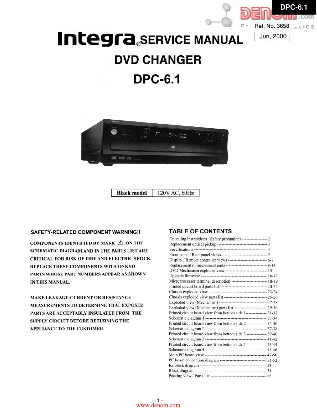
Integra dpc 6 1 service manual

This is the 31 pages manual for integra dpc 6 1 service manual.
Read or download the pdf for free. If you want to contribute, please mail your pdfs to info@audioservicemanuals.com.

Page: 1 / 31
left right
integra dpc 6 1 service manual

Extracted text from integra dpc 6 1 service manual (Ocr-read)


Page 1

l ' Ref. No. 3658

Integra®SERVICE MANUAL £99001"

DVD CHANGER

DPC-6.1

Black model 120V AC, 60Hz

SAFETY-RELATED COMPONENT WARNING

COMPONENTS IDENTIFIED BY MARK A ON THE
SCHEMATIC DIAGRAM AND IN THE PARTS LIST ARE

CRITICAL FOR RISK OF FIRE AND ELECTRIC SHOCK.

REPLACE THESE COMPONENTS WITH ONKYO
PARTS WHOSE PART NUMBERS APPEAR AS SHOWN
IN THIS MANUAL.

MAKE LEAKAGE-CURRENT OR RESISTANCE
MEASUREMENTS TO DETERMINE THAT EXPOSED
PAR l'S ARE ACCEPTABLY INSULATED FROM THE
SUPPLY CIRCUIT BEFORE RETURNING THE
APPLIANCE I'U [HE CUSIUMLK.

_1_

TABLE OF CONTENTS

Operating instructions . Safety precaution
Replacement optical pi
Specifications -
Front panel J Rear panel \ICW
Display « Remote controller \iei
Replacement ofmcchanical pans -
DVD Mechanism exploded 'cvt »
Upgrade IIl'mVHllt ----------
Microprocessor terminal description
Printed Circuit board pans I
Chassis exploded \ ieVi -----
Chassis exploded View pans list
hxplodcd Vic (Mechanism) "-
Iixplodcd \ icw (Mechanism) pans llb
Irinied circuit board View from bottom side 1-
Schematic diagram I ---------------------------
Printed circuit board VIC from bottom side 2
hchematic diagram 1 --
Printed circuit board c from bottom Side 3
Schematic diagram 3 --
Printed circuit board \ievi from bottom side 4
Schematic diagram 4 --
Mam PC board \ievi --
PC board connection diagram
lcs block diagram
Block diagram -
Packing \ieti r Parts list -


www.den0m.c0m

Page 2

DPC

SAFETY PRECAUTIONS

WARN I NG The IIgntnIng flash wnh arrowhead symbol, wnhin an equtlateral triangle. Is
RISK OF ELECTRIV SHOCK intended to alen the user to the presence oi uninsulated dangerous voltage"
within the product's enclosure that may be oI sufficient magnitude to constitute

a risk of electric shock to persons,
ISOUE DE ottoc ELEctRmtE NE

VEIEEEIRISC- SHggKREDUgg TuETR I REESE The exclamation point within an equilateral triangle is Intended to alert the user
COVER (OR BACK) ' N0 USERSERV | CEABLE to the presence of important operating and maintenance (sen/tong) Instruction
pun | NS I DE, ' REFER SERVICING T0 in the literature accompanying the appliance.

DUAL | F | ED SERV | CE PERSONNEL.


WARNING : TO REDUCE THE RISK OF FIRE OR ELECTRIC SHOCK, DO NOT EXPOSE THIS APPLIANCE To RAIN
OR MOISTURE. DANGEROUS HIGH VDLTAGES ARE PRESENT INSIDE THE ENCLOSURE. DO NOT OPEN THE
CABINET. REFER SERVICING To QUALIFIED PERSONNEL ONLY.

CAUTION : TO PREVENT ELECTRIC SHOCK, MATCH WIDE BLADE OF PLUG TO WIDE SLOT, FULLV INSERT.

AI IENIION : POUR Evt I EH LES UHUCS ELEUIHIOUE, INIRODUIRE LA LAME LA PLUS LARGE DA LA FICHE DANS LA
BORNE CORRESPONDANTE DA LA PRISE ET POUSSER JUSQU' AU FOND.

Replacing the fuse

For continued protection against risk fire, replace only
with same type and same rating fuse.

CIRCUIT No. PART No. DESCRIPTION
F901 252157 1.25A-U1/T-237

«I:}- This symbol located near the {use indicates that the fuse
used is last operating type. For continued protccuon against fire
hazard. replace with same type fuse. For fuse rating refer to the
marking adjacent to the symbol.

-.:|- Ce symbole indique que Ie fusible utlise est a rapide.
Pour une protectton pctmancntc. n utIlIser quc des tumbles dc meme
type. Ce darmier est indique Ia qu I: present symbol csl appose

LASER BEAM CAUTION LABEL

WON ~ VISIBLE LASER RADIATION WHEN OPEN
AND INTEHLOCK DEFEATED
DO NOT suns mm BEAM

ADVARSEL ~ LASERSYRALING VED Aenws, Nita
SIKKERHEDSAFBRVDERE EH UDE AF
FUNKYICN sE IKKE IND I smug»:

ADI/ARSELr LASERTRALING N a DEKSEL XPNEs

OG leKERHEDsL s BRVTES
STIRR lKKE INN l STRALEN

VAFNING ostLIG LASERSYRXLNING NAFl__DENNA

DEL AR ODPNAD OCH SFARRAR An

WAVE LENGTH '650nm URKOFPLADE STIRRA EJ IN I STRALEN
MAX LASER POWER :OISmW vARo' .AVATTAESSA JA SUOJALUKITUS

. oHIrErrAEssA OLET ALTTHNA LASER

l l . 350' sxrsILVLLE ALA wuom SATEESEEN
IXJ b-f-flm : 0.5Irl :3 . -uur:uuttrru=uveeamp~or-aw

b l) 11'. e-Atlur; out": I) LIJIA: t.

SN 29352504

When the power supply is being turned on, you may not remove this laser cautions

label, radiation of a laser may he received.

Pickup Head consists of a laser diode that is very susceptible to external static electricity.
Although it operates properly after replacement. if it was subject to electrostatic discharge
during replacement. its life might be shortened. When replacing. use a conductive mat.
soldering iron with ground wire. etc. to protect the laser diode from damage by static
electricity. And also. the LS] and It i are same as ahnw.

_ 2 _
www.den0m.c0m