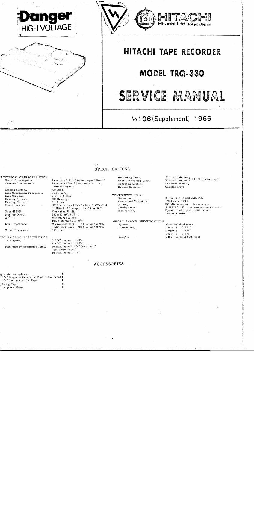
Hitachi TRQ 330 Service Manual

This is the 10 pages manual for Hitachi TRQ 330 Service Manual.
Read or download the pdf for free. If you want to contribute, please mail your pdfs to info@audioservicemanuals.com.

Page: 1 / 10
left right
Hitachi TRQ 330 Service Manual

Extracted text from Hitachi TRQ 330 Service Manual (Ocr-read)


Page 1

H

Hitachi. Ltd. Tokyo Japan

ger
HIGH VOLTAGE

HITACHI TAPE RECORDER

MODEL TRQ-33O

No.106(Supplement) 1966

(x
SPECIFICATIONS
.LECTRICAL CHARACTERISTICS. Rewindmg TIme. wnmn 2 mmules ., _
Power ConsumpuonI Less man 1.8 \\ I \udIo oquut 200 m\\') Fas: Forwardmg Txme, wnhm 4 mmules} 3 °° ""m 99"
Current Consumpnom Less than IsomHPIzyIng conduion, Operaling Sysmn, one knob control.
without signal? Driving Syszem. Capsxan drive.
Busing System. AC BiasI
Bias OscIllakion Frequency. 35 1 1 kc/s.
8135 Current . D. E - 1.0 mAI COMPONENTS USED.
Erasing System. DC Erasmg. TransIsmrs_ 25373, 25375 and 25377.
Erasing Curran. 3 _ 5 my Blades and Van'smrs. man and IIVIs.
Power Source. DC 9 V bauery (UM-2 x s or 6"C cellsl Motor. DC MIcro-mozor wuh governor,
or mach. Ic adaptor WA or 905 Loudspeaker. 4 x 2. 3/4" Oval permanent magnn typeI
Overall S/N. More man 35 dB. Microphane, DynamIc microphone \th remote
MonIQr OutpulI 250 r. 50 mV/S Ohm. comml Witch-
0 f - Maamum 500 m,
7" disumm 20° "W' MISCELLANEOUS SPECIFICATIONS.
Input Impedance, Mlcrophone Jack. 2 k-uhm(Approx.) syswm Monaural dun! 36L
RadIo Input Jack zoo krohmulpprox.) Dimensms Wm", . 10.114
OquuI Impedance. 3 Ohms, fight : 2 5/3"
Depth 8. 5/3"
IECHANICAL CHARACTERISTICS Wenghl. 5 Ibs (Ilhoul hunches)
Tape Speed. 3. 3/4" per sccond+3"a.
1,7/3" per serondt3,o.
Mammum Performance TIme. 2o mmules at 3 3/4" (mu-cm 3"
50 micron tape.)
40 mInutes 311,7/5"
ACCES SO RIES I
Iynamic nucrophone. I

1/4" Magneuc Recordmg TapeJSO mmon) I.
.1/4" Empty Reel ror Tape
phcing Tape. I.
IIcrophone Case. I.

Page 2

MODEL TRQ-33O SERVICE MANUAL

n:«..;,v.a.4 ..

DES CRIPTIONS

1, Dry Cell Operated

Because it is operated simply by dry-cells.
you can enjoy anywhere and anytime re-
gardless of indoor or outdoor.

Level Mutic Device

For the excessive impulseic input, it works
remarkably, resulting distortionless re-
cording.

3. All TranSistor System

Electrical circuit start its operation in-
stantaneously and simultaneously with tape
driving mechanisms.

4 Micromotor

High quality micrometer providing goverv

CIRCUIT

Those devices, such as micro-phone and magne-
tic recording head, connected to the first stage
usually change their impedance with frequency.
At the time of recording, either micro-phone or
radio-58L output may be connected, while in case
of play-back, magnetic recording head will be
connected.

In case of Radio Input
R1 and R2 are connected in series and they

work as voltage divider as illustrated in Fig. 1.

In case of Micro-phone Input

R2(2.2k-ohm) is connected in series with

1%

FIRST AND SECOND STAGE

Impedance matching of the input circuit with ex-
ternal devices such as microphone, radio-set
and magnetic recording head are taken into con-
sideration as were described above. Matching
between input circuit and transistor input impe-
dance is, however, not obtained exactly, because
of the satisfactory gain of the succeeding ampli-
fiers. this amount of matching loss is acceptable.
See Fig. 3.

A circuit thh R.C is depicted in Fig.4e-ethat
is R,C filter circuit and the function of it is to
lead radio broadcast signal to the ground. It the
places where thi> field strength is strong, RF
signals caught at microphone (being an inductive
deuce, it may work as an antenna in some case)
Will be detected by emitter-base diode and be
converted into audio signal to bring music or
speech being broadcastcd.

nor presents steady constant running of
tape for long time.

3. Monitoring

Output JaLk may be used as monitor output
jack, also at the time of recording,

6. Tape Speed

Two speeds are available by means of caps-
tan collar changing.

7. Earphone for Private Listening and Monitor-
mg,

8. Operation with Power Mains Available

By means of AC adaptor, you can enjoy with
"power mainsI voltage.

EXP LANATION

micro~phone to regulate audio current against
impedance change caused with difference of fre-
quency.

In case of Play-back
As the magnetic recording head itself is simp-

ly an inductive device, impedance increases in
proportion to frequency to be reproduced. To
keep the input voltage for TR1 as constant as
possible, a considerably big resistor R4(39 k-
ohm) is employed as current regulator. That is,
as illustrated in Fig 2, R4 and R5 are connected
in series with changing head impedance Zo.

MEAD

HEAD IMFEDANC-E]


l
l
(ZKMOOO9S):
I
1
5
HEAD EM; 0
.' R6
I sax
l -9
Fig.2
cs
0.0:: EEK
Zlok zu
Zia cs zn

mo
R9 l8
$12K

Fig. 3