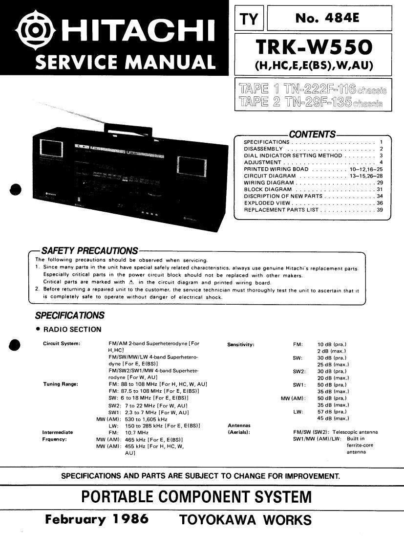
Hitachi TRKW 550 Service Manual

This is the 50 pages manual for Hitachi TRKW 550 Service Manual.
Read or download the pdf for free. If you want to contribute, please mail your pdfs to info@audioservicemanuals.com.

Page: 1 / 50
left right
Hitachi TRKW 550 Service Manual

Extracted text from Hitachi TRKW 550 Service Manual (Ocr-read)


Page 1

TY No. 484E
@ HITACHI TRK-W550

SE RVI C E MA N UAI. (H,HC,E,E(BS),W,AU)

TAPE fl TRIGQZQFDW
TAPE T/Q Tll\%3EalJ%5

7%
n l

CONTENT S-x
SPECIFICATIONS ..................... 1
DISASSEMBLY ...................... 2
DIAL INDICATOR SETTING METHOD A . . . . 3
ADJUSTMENT ....................... 4
PRINTED WIRING BOAD ......... 10-12,16-25
CIRCUIT DIAGRAM ......... 13-15,26-28
WIRING DIAGRAM .......... , 29
BLOCK DIAGRAM ......... . . , .31
DISCRIPTION OF NEW PARTS ............ 34
EXPLODED VIEW ..................... 36
REPLACEMENT PARTS LIST .............. 39
k J
SAFETY PRECAUTIONS
The followmg precautions should be observed when servrcmgl
1. Smce many parts in the UNIX have specral 531er related characteristics. always use genuine Hltachls replacement parts.
Espec-ally critical parts in the power crrcuit block should not be replaced With other makers,
Crmcal parts are marked with A In the crrcult dlagram and primed wrung board.
2. Belore returning a repaired unit to the customer, the service technician must thoroughly test the um: to ascertain that I!
is completely safe to operate wlthou! danger ol elecmcal shock.
SPECIFICATIONS
. RADIO SECTION
. Circuit Systam: FM/AM 2-band Superheterodvne [For sgnsmmy: FM: 10 dB (pram)
HIHCI 2 dB (maxJ
FM/SW/MW/LW 4-band Superhetero- sw; 30 dB (pm)
dY"? [For E, EIBSII 25 dB (max.l
FM/SWZ/SWl/MW 4-band Superhete- swz; 30 d8 (praJ
rodyne [For W, AU) 20 dB (maxJ
Tuning Range: FM: 88 {0108 MHz [For H4 H6, W, AU! SW1: 50dB (Dra.l
FM: 87.5t0108MHZIForE,ElBSl] 35dB (max)
SW: 6 to 18 MHz [For E, ElBSl] MW (AM)? 50 dB (WE-I
SW2: 7 to 22 MHz [For W, AU] 35:18 (max)
SW1: 23 «)7 MHz [ForW, AU] LW: 57dB IONS.)
MW (AM): 530 to 14605 kHz 45 dB (max)
LW: 150 to 285 kHI [For E, EIBSH Antennas
Intermediate FM: 10.7 MHz (Aerials): FM/SW (SW2): Telescopic antenna
Frquencv: MW (AM): 465 kHz [For E, ElBSH SW1/MW (AMI/LW: Built in
MW (AM): 455 kHz [For H, HC, W, ferrite~core
AU] antenna

SPECIFICATIONS AND PARTS ARE SUBJECT TO CHANGE FOR IMPROVEMENT.

PORTABLE COMPONENT SYSTEM

February 1986 TOYOKAWA WORKS

Page 2

TRK-W550 I

0 TAPE RECORDER SECTION 0 GENERAL SECTION
Tape: Cassette tape Semiconductors: le: 10 [For H, HC, W, AU]
Track System: 4 track 2 channel stereo 11 [For E, EiBSl]
Tape Speed: - 4.75 cm/sec: Translstors: 23 (For H, HC, W, AU]
Recording System: AC bias (TAPE 2) 24 [For E, E(BS)]
Erosinq System: AC erase (TAPE 2) Diodes: 25 [For W, AU]
Frequency 24 [Except W, AU]
Response: Normal: 30 to 13,000 Hz LEDs: 3
METAL: 30 to 14,000 Hz Power Supply: AC: 120 V, 60 Hz [For H, HC]
Signal to Noise AC: 220 V, 50 Hz [For E]
Ratio: 50 dB AC: 240 V, 50 Hz [For E (88), AU]
Wow and Flutter: 0.08% (W-RMS) AC: 110 -127V/200 - 220Vl230 '-
Cross Talk: Between tracks: 65 dB 250V,50l60Hz [For M
Between channels= 40 dB DC: 15 v ("D" CELL (iEC R20lx 10
Output Load or equivalent)
Impedance: Mlxlng mic:1.6 mV, 4 kn Power Consumption: 30W [For W!
Llne-ln: 600 mV, 47KB [For H, HC, W, AU] 35w (For H, HC]
CD-in: 650 mV, 47m [For H. HC,W, AU] 45w [For E, EKBS), Au]
Phone-in: 6 mV, 47 kn [For E, E(BSl] Power Output: 60 W P.M.P.(AC operation)
0 L CD/Llne-ln:650mV. 47km [For E, EiBSl] [Except H, HC]
utput owl and
MW... m
Distortion: :eakers 2'8 to 8 n - . Tweeter: 2 cm, 500 0 (X4) .
Erasing Ratio: 65w DI'lImSIons: 642 (w) )5 230 (H)'x 188 (D) mm
Fest Forwarding or Wlllm: 8.0 kg (wrth batteries)
Rewinding time: TAPE 1: 120 sec
TAPE 2: 150 sec
Motor: DC motor
DISASSEMBL Y

1. How to remove the speaker box (Fig .1)
Release one clip to the arrow direction and remove the
speaker box by pulling upward. (both side) Cassette doors

Speaker box /

Mic volume
control knob

Graphic equalizer
oontrol knobs

Volume control knobs

0' Fig.2

Fig.1

2.How to remove the Front panel (Fig. 2, 3)
Remove two screws 6) , three screws ® and one
screw ® which is in the battery case.
Then open the cassette doors and pull the front panel.
(Screw ® is except W, AU)

Note.Eight knobs come off toqether when pull the
front panel.