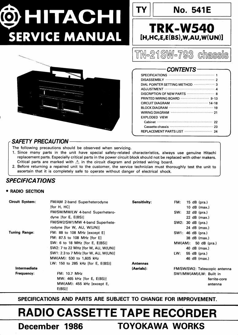
Hitachi TRKW 540 Service Manual

This is the 28 pages manual for Hitachi TRKW 540 Service Manual.
Read or download the pdf for free. If you want to contribute, please mail your pdfs to info@audioservicemanuals.com.

Page: 1 / 28
left right
Hitachi TRKW 540 Service Manual

Extracted text from Hitachi TRKW 540 Service Manual (Ocr-read)


Page 1

TY N . 541E
(9) HITACHI TRK :N540
SERVICE MANUAL m(3:),w,Au,w

TNuZflSWn7®3 chaeeie

r- CONTENTS -w
SPECIFICATIONS . ~
DISASSEMBLY ~~
DIAL POINTER SETTING METHOD
ADJUSTMENT ------------------
DISCRIPTION OF NEW PARTS
PRINTED WIRING BOARD
CIRCUIT DIAGRAM -
BLOCK DIAGRAM
WIRING DIAGRAM ........................................ 21
EXPLODED VIEW
Cabinet ------------------
Cassette chassis
REPLACEMENT PARTS LIST

SAFETY PRECAUTION

The following precautions should be observed when servicing.

1. Since many parts in the unit have special safety-related characteristics, always use genuine Hitachi
replacement parts, Especially critical parts in the power circuit block should not be replaced with other makers.
Critical parts are marked with A in the circuit diagram and printed wiring board.

2. Before returning a repaired unit to the customer, the service technician must thoroughly test the unit to
ascertain that it is completely safe to operate without danger of electrical shock.

SPEC/FICA TIONS
o RADlO SECTION

Circuit System: FM/AM 2-band Superheterodyne Sensitivity: FM: 15 dB (pra.)
[for H, HC] 10 dB Imax.)
FM/SW/MW/LW 4-band Superhetero- SW: 32 dB lpra.)
dyne [for E, EIBSl] 22 dB (max.)
FM/SW2/SWI/MW 4~band Superhete- SW2: 30 dB (pra.)
rodyne [for W, AU, WIUNll 24 d8 (mexJ
Tuning Range: FM: 88 to 108 MHz [except E] SW1: 46 dB lpra.)
FM: 87,5 to 108 MHz [for E] 38 dB Imax.)
SW: 6 to 18 MHz [for E, EIBS)] MW(AM): 50 dB Ipra.)
SW2: 7 to 22 MHz [for W, AU, WIUNII 40 dB (max.)
SWI: 2.3 to 7 MHz [for W, AU, WIUN)! LW: 55 dB (pra.)
MW(AM): 530 to 1,605 kHz 46 dB (max.l
LW: 150 to 285 kHz [for E, EIBSII Antennas
Intermediate (Aerials): FM/SW/SWZ: Telescopic antenna
Frequency: FM: 10.7 MHz SW1/MW(AM)/LW: Built in
MW: 465 kHz [for E, E(BS)] ferrite-core
MW(AM): 455 kHz [except E, antenna
EIBSII

SPECIFICATIONS AND PARTS ARE SUBJECT TO CHANGE FOR IMPROVEMENT.

RADIO CASSETTE TAPE RECORDER
December 1986 TOYOKAWA WORKS

Page 2

TR K-W540

0 TAPE RECORDER SECTION

Tape: Cassette tape

Track System: 4 track 2 channel stereo
Tape Speed: 4.75 cm/sec.

Recording System: AC bias (TAPE 2)
Erasing System: Magnet erase (TAPE 2)
Erasing Ratio: 65 113

Frequency Response: Normal: 60 to 10,000 Hz
Signal to Noise

Ratio: 40 dB
Wow and Flutter; 0.25% (W~RMS)
Cross talk: Between tracks: 65 dB

Between channels: 35 dB

lmput sensitivity and

impedance: CD/Line-inz700mv, 100k!)

Output Load

impedance: Headphone 8 to 1000
Speakers 4 to 8.0

Distortion: 3%

Motor: DC micro motor

Head: Permalloy

DISASSEMBLY

1. Speaker box (Fig. 1)

2.

Remove one clip to the arrow direction and remove the
speaker box by pulling upward. (both side)

Speaker box

Fig.1

Front case (Fig. 2)
Remove four screws @, one screw ® and one screw (3

which is in the battery case.

0 GENERAL SECTION

Semiconductors: ICs: 5
Transistors: 17 [for H, HC]
18 [for W, AU]
20 [for E, E(BS)]

Diodes: 11 [for E, E(BS), AU]
12 (for H, HC, W, W(UN))
LEDs: 2
Power supply: AC: 120 V, 60 Hz [for H, HC]

AC: 220 V, 50 Hz [for E]
AC: 240 V, 50 Hz [for Elle, AU)
AC: 110-127V/2007220V/230
-250V, 50/60Hz [for W, WlUN)]
DC: 12 V IEC R20 ("D" CELL) X 8
or equivalent)
Power Consumption: 18 W (except H) 14 W (for H)
Power Output: 60 W P.M.P. (AC operation)
[except H, HC]
3.5WICH (10% T.H.D. DC operation)

Speakers: Woofer: 12 cm, an (X2)

Tweeter: 2 cm, 3000 (X2)
Dimensions: 580 (W) X220 (H) X 189 (D) mm
Weight: 5.9 kg (with batteries)


Front case

Battery cover

3. MAIN P.W.B. and GRAPHIC EOUALIZER P.W.B. (Fig. 3)
Remove one screw @. Pull the GRAPHIC EOUALIZEH
P.W.B. and MAIN P.W.B., then remove five connectors.
Release three clips to the arrow direction.

GRAPHIC EOUALIZER P.W.B.

Connectors