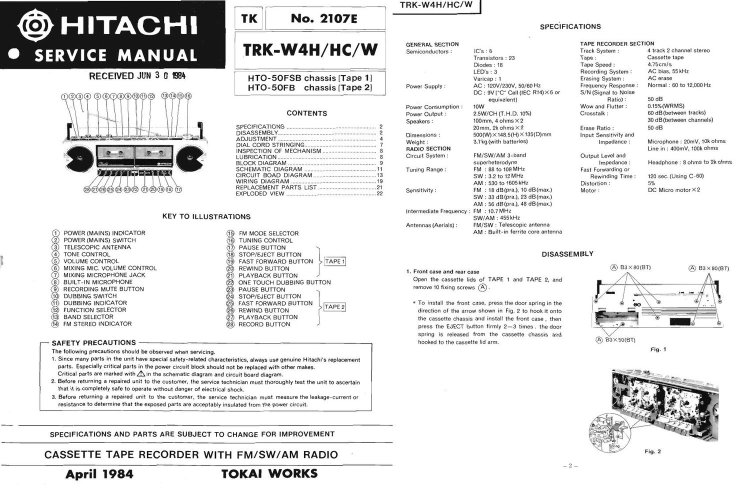
Hitachi TRKW 4 H Service Manual

This is the 16 pages manual for Hitachi TRKW 4 H Service Manual.
Read or download the pdf for free. If you want to contribute, please mail your pdfs to info@audioservicemanuals.com.

Page: 1 / 16
left right
Hitachi TRKW 4 H Service Manual

Extracted text from Hitachi TRKW 4 H Service Manual (Ocr-read)


Page 1

@HITACHI

SERVICE MANUAL

RECEIVED JUN 3 E} as!»

POWER (MAINS) INDICATOR
POWER (MAINS) SWITCH
TELESCOPIC ANTENNA
TONE CONTROL

VOLUME CONTROL

MIXING MIC. VOLUME CONTROL
MIXING MICROPHONE JACK
BUILT-IN MICROPHONE
RECORDING MUTE BUTTON
DLIBBING SWITCH
DUBBING INDICATOR
FUNCTION SELECTOR
BAND SELECTOR

FM STEREO INDICATOR

SAFETY PRECAUTIONS

we

No. 2107E

TKl

'I'RK-W4H/ HC/ W

HTO-SOFSB chassis [Tape 1]
HTO-SOFB chassis [Tape 2]

CONTENTS

SPECIFICATIONS
DISASSEMBLY..
ADJUSTMENT.
DIAL CORD STRINGING .........
INSPECTION OF MECHANISM
LUBRICATION .........
BLOCK DIAGRAM ..
SCHEMATIC DIAGRAM ..


CIRCUIT BOAD DIAGRAM 13
WIRING DIAGRAM .............. 19
REPLACEMENT PARTS LIST 21
EXPLODED VIEW .................... ...22

KEY TO ILLUSTRATIONS

GE

@®®®®®®®®©®9®

FM MODE SELECTOR
TUNING CONTROL
PAUSE BUTTON
STOP/EJECT BUTTON
FAST FORWARD BUTTON
REWIND BUTTON
PLAYBACK BUTTON

ONE TOUCH DUBBING BUTTON
PAUSE BUTTON
STOP/EJECT BUTTON
FAST FORWARD BUTTON
REWIND BUTTON
PLAYBACK BUTTON
RECORD BUTTON

The following precautions should be observed when servicing.

1. Since many parts in the unit have special safety-related characteristics, always use genuine Hitachi's replacement
parts. Especially critical parts in the power circuit block should not be replaced with other makes.
Critical parts are marked withAin the schematic diagram and circuit board diagram.

2. Before returning a repaired unit to the customer, the service technician must thoroughly test the unit to ascertain
that it is completely safe to operate without danger of electrical shock.

3. Before returning a repaired unit to the customer, the service technician must measure the leakage-current or
resistance to determine that the exposed parts are acceptably insulated from the power circuit.

GENERAL SECTION
Semiconductors :

Power Supply :

Power Consumption :
Power Output :
Speakers :

Dimensions :
Weight :

RADIO SECTION
Circuit System :

Tuning Range :

Sensitivity :

Intermediate Frequency :

Antennas (Aerials) :

TRK-W4H/HC/W I

SPECIFICATIONS

lC's : 6

Transistors : 23

Diodes 2 18

LEDs : 3

Varicap : 1

AC : 120V/280V, 50/60 Hz

DC: 9V [C Cell (lEC R14)><6 or
equivalent]

10W

2.5W/CH (T.H.D. 10%)

100mm, 4 ohmsX2

20 mm, 2k ohmsX 2

500(W)><148.5(H)X135(D)mm

3.7 kg (with batteries)

FM/SW/AM 3-band
superheterodyne

FM : 88 to 108MHz

SW: 3.2 to 12 MHZ

AM : 530 to 1605 kHZ

FM ; 18 dB(pra.), 10 dB(max.)
SW : 33 dB(pra.), 23 dB(max.)
AM : 56 dB(pra.), 48 dB(maxt)
FM : 10.7 MHz

SW/AM : 455 kHz

FM/SW : Telescopic antenna

AM : Built-in ferrite core antenna

TAPE RECORDER SECTION

Track System :
Tape :

Tape Speed :
Recording System :
Erasing System :

Frequency Response -.

S/N (Signal to Noise
Ratio) :

Wow and Flutter :

Crosstalk :

Erase Ratio :
Input Sensitivity and
Impedance :

Output Level and
Impedance :
Fast Forwarding or

Rewinding Time :

Distortion :
Motor :

DISASSEMBLY

1. Front case and rear case

Open the cassette lids of TAPE 1 and TAPE 2, and

remove 10 fixing screws @.

SPECIFICATIONS AND PARTS ARE SUBJECT TO CHANGE FOR IMPROVEMENT

CASSETTE TAPE RECORDER WITH FM/SW/AM RADIO

April 1984

TOKAI WORKS

* To install the front case, press the door spring in the
direction of the arrow shown in Fig. 2 to hook it onto
the cassette chassis and install the front case , then
press the EJECT button firmly 2-3 times. the door
spring is released from the cassette chassis and
hooked to the cassette lid arm.

@ BS >< amen

4 track 2 channel stereo
Cassette tape

4.75cm/s

AC bias, 55 kHz

AC erase

Normal : 60 to 12,000 HZ

50 d B

0.15% (WRMS)

60 dB(between tracks)
30 dB(between channels)

50 dB

Microphone: 20mV. 10k ohms
Line in : 400mV,100k ohms

Headphone : 8 ohms to 2k ohms
120 sec. (Using C-GO)

5%
DC Micro motor X 2

® Ba x 80(BT)

Page 2

TRK-W4H/HC/W I

2. Cassette lid
Push the cassette lid arm in the direction of arrow.

Frame chassis


ADJUSTMENT

1. Radio Section

\ Measuring Instrument and Connection Genescope Dial
Ma'n PC Board Adjustment or Signal . . .
I Step Item Measuring Input Output Generator Pornter Adjust Readlng
Instrument Terminal Terminal Frequency' Posrtron
- Genescope 10:] MHz
1 (1) FM IF 10-7 MHZ) TP103 TP301 Highest T101 Note 1
108 MHZ 108 MHz
2 owes
(1) 87 MH L t L102 M
, F - FM 080. . FM signal . -
V 2 fl (Covering) generator TP101 102 109 MHz Highest CT102
Fi a 5m ers Stoppers B3X20 9' pp (3) ' ° (thru FM Speaker Repeat steps (1) and (2)
Fig. 5 . 31min) dummy terminal
. (1) ' V-f-fi/lll/liscope antenna) (4ohm load) 90 MHz 90 MHz L101
3. One touch dubbing button 7_ Cassette chassis - FM ANT (Note 2) Max.
Press the stopper of the front case using a fine flat-tip Tape 1 1 Remove 2 fixing screws ©. 3 (2) (Tracking) 106 MHZ 105 MHZ CT101
screwdriver In the direction of the arrow to remove it. Tape 2 : Remove 2 fixing screws ® . (3) Repeat steps (1) and (2)
FM MPX - Frequency 19 kHz
3- Speaker 4 (1) (Multiplex) counter Note 3 RT301 i100 Hz
Push the speaker to remove it in the direction of the .
arrow - Genesco e Ferrlte-core .
- 5 (1) AM IF (455 kHz) antenna l'P301 455 kHz Highest - Note 5
(Note 4)
(1) 3.1 MHz Lowest L153
@ 33X10(BT) © BSX10(BT) 7 SW 050 Max.
6 (2) (C . ' - AM Signal 12.5 MHz Highest CT158
' ' 7 overing) generator Ferriteacore Speaker
(3) (400 Hz, 30% antenna terminal Repeat steps (1) and (2)
One touch dubbing button mod.) (Note 4) (4ohm load)
. ., . . , ~ VTVM
One touch dubblng button >
Fig. 4 7 (1) SW ANT. 4 MHZ 4 MHz L151 Max.
_ (Tracking)
4 Handl (2) Repeat steps (1)and (2)
. e
Insert a flat-tip screwdriver into the position shown in _ 2 515 kHz Lowest L154 Max
Fig. 5 to release the lock. F'g' 6 8 (2) AM 0.80 1650 kHz Hi hest CT152
(Coverm ) g
- g - AM signal S k d
. (3) generator Ferrite-core pea er Repeat steps (1) an (2)
5. Radio PC Board (400 Hz, 30% antenna terminal
Press 2 stoppers outside the board to release them. (1) mod.) (Note 4) (4ohm load) 600 kHz 600 kHz L152
i AM ANT 'VTVM k C Max.
' 1400 H 140 kH T151
6. Main PC Board 9 3 (Tracking) Z 0 Z
1) Remove 3 knobs (Tone, Volume, Mic volume) and 2 (3) Repeat steps (1) and (2)
fixing screws .,
2) Pull the LINE IN jack board toward the front to remove Note
it. 1. S-curve adjustment is not required but confirm that the 2' FM dummy antenna shows Figure 8.

waveform is as shown in Fig. 7. Adjust T101 so that the
noise at the center of the S-curve is minimum and the
noise at the base line is maximum.

3) Remove 2 stoppers and pull the board toward the
front while lifting its bottom to remove the board from
the frame chassis.

FM dummy antenna

Signal generator

B
C
Base line
A
Fig. 7 R9 : SG's output impedance

Fig. 8