Hitachi TRK 9900 E Service Manual

This is the 31 pages manual for Hitachi TRK 9900 E Service Manual.
Read or download the pdf for free. If you want to contribute, please mail your pdfs to info@audioservicemanuals.com.

Page: 1 / 31
left right
Hitachi TRK 9900 E Service Manual

Extracted text from Hitachi TRK 9900 E Service Manual (Ocr-read)


Page 1

TK H No.1614E

@ HITACHI
SERVICE MANUAL TRK'99OOErilB-tl

CONTENTS

Specifications .................. 2
Disassembly .................... 2
Adjustments .................. 6
Dial cord stringing ............... 9
Inspection of mechanism .......... 10
Lubrications .................. 10
Replacement parts list ............ 11
Exploded view ................. 15
Schematic diagram .............. 18
Circuit board diagram ............ 21
Wiring diagram ................. 34
Block diagram ................. 37

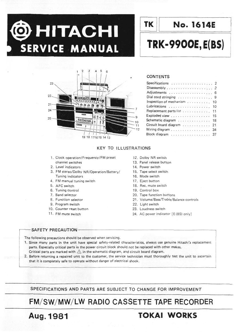
19181716151413

KEY TO lLLUSTRATIONS

1. Clock operation/Frequency/FM preset 12. Dolby NR switcn
channel switches 13. Panel release button
2. Level indicators 14. Power switch
3. FM stereo/Dolby NR/Operation/Battery/ 15. Tape select switch
Tuning indicators 16. Mode switch
4. FM manual tuning switch 17. Eject button
5. AFC switch 18. Rec. mute switch
6. Tuning control 19, Control box
7. Band selector 20. Tape function buttons
8. Function selector 21. Volume/Bass/Trebie/Balance controls
9, Program switch 22. Light switch
10. Counter reset button 23. Loudness switch
11. FM mute switch 24. AC power indicator [E (BS) only]

r SAFETY PRECAUTION ** _,

The following precautions should be observed when servicing.

1. Since many parts in the unit have special safety-related characteristics, always use genuine Hitachis replacement 1
parts. Especially critical parts in the power circuit block should not be replaced with other makes.
Critical parts are marked with A in the schematic diagram, and circuit board diagram.

2. Before lemrning a repaired unit to the customer, the service technician must thoroughly test the unit to ascertain
that it is completely safe to operate without danger of electrical shock.

SPECIFlCATIONS AND PARTS ARE SUBJECT TO CHANGE FOR IMPROVEMENT

FM/SW/MW/LW RADIO CASSETTE TAPE RECORDER

Aug. 1981 TOKAI WORKS