Hitachi TRK 6835 Service Manual

This is the 18 pages manual for Hitachi TRK 6835 Service Manual.
Read or download the pdf for free. If you want to contribute, please mail your pdfs to info@audioservicemanuals.com.

Page: 1 / 18
left right
Hitachi TRK 6835 Service Manual

Extracted text from Hitachi TRK 6835 Service Manual (Ocr-read)


Page 1

TY No. 581 E

(9) HITACHI

SERVICE MANUAL

TR K-6835

(E, E(BS))

TIN] DESSEZV: @OI cheeefie

)

CONTENTS

KEY TO ILLUSTRATIONS .............. I
SPECIFICATIONS ..................... 2
MAINTENANCE ....................... 2
DISASSEMBLY ..................... 2.3
INSPECTION OF MECHANISM ......... 3
LUBRICATION ........................ 4
DIAL CORD STRINGING ............... 4
ADJUSTMENT ..................... 4-6
PRINTED WIRING BOARD ............. 7
CIRCUIT DIAGRAM ................. 8,9
BLOCK DIAGRAM ................... 10
EXPLODED VIEW ................. 11,12
REPLACEMENT PARTS LIST ....... 13,14

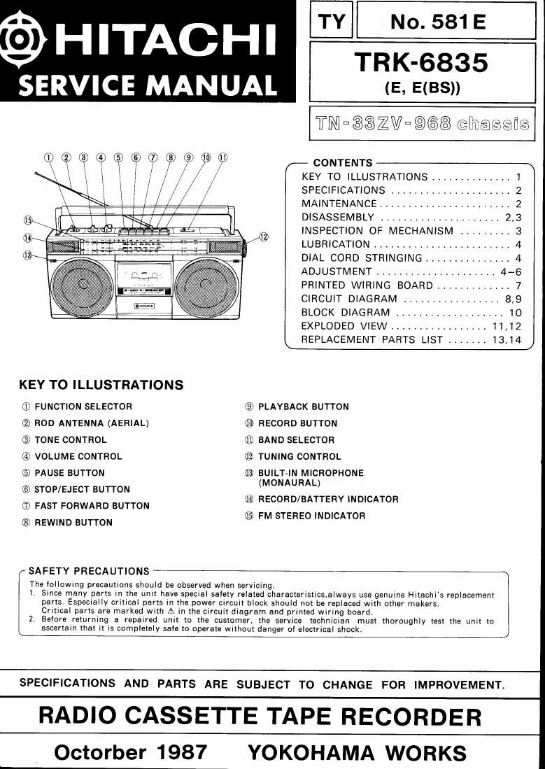
KEY TO ILLUSTRATIONS

(1) FUNCTION SELECTOR © PLAYBACK BUTTON

® ROD ANTENNA (AERIAL) 69> RECORD BUTTON

® TONE CONTROL ® BAND SELECTOR

@ VOLUME CONTROL 62> TUNING CONTROL

(5) PAUSE BUTTON ® BUILT-IN MICROPHONE

(MONAURAL)

CED STOP/EJECT BUTTON
(73 FAST FORWARD BUTTON
® REWIND BUTTON

® RECORD/BATTERY INDICATOR
(133 FM STEREO INDICATOR

SAFETY PRECAUTIONS

The following precautions should be observed when servicing.

I. Since many parts in the unit have special safety related characteristics,always use genuine Hitachis replacement
parts. Especially critical parts in the power circuit block should not be replaced with other makers
Critical parts are marked with A in the circuit diagram and printed wiring board.

2 Before returning a repaired unit to the customer, the service technician must thoroughly test the unit to
ascertain that it is completely safe to operate without danger of electrical shock,

SPECIFICATIONS AND PARTS ARE SUBJECT TO CHANGE FOR IMPROVEMENT.

RADIO CASSETTE TAPE RECORDER

Octorber 1987 YOKOHAMA WORKS

Page 2

TRK-6835

SPECIFICATIONS
GENERAL SECTION ' Antennas (Aerials) : FM/SW : Rod antenna
Semi-conductors : IC's : 5 (aerial)
Transistors : 5 (E) MW/LW : Built-in ferrite-core
4 [E(BS)] antenna (aerial)
Diodes : 5 TAPE RECORDER SECTION
LED's : 2 Tape : Cassette tape
Zener diode : 1 Tape Speed : 4.75cm/s
Power (Mains) Recording System : AC bias
Supply : AC : 220V, 50Hz (E) Erasing System : Magnet
240V, 50Hz [E(BS)] Track System : 4 track 2 channel
DC : 9V Frequency Response : Normal : 80Hz to 10kHz
(IEC R20 X 6 or equivalent) S/N (Signal to Noise
Power (Mains) Ratio) : 43 dB
Consumption : 8W Wow and Flutter : 0.25% (WRMS)
Dimensions : 454(W) >< 209(H) >< 121(D) mm Crosstalk : 65 dB (Between tracks)
Weight : 3.3kg (with batteries) 40 dB (Between channels)
Power output : 5W P.M.Pt (AC operation) Erase Ratio : 60 dB
1.2W/ch (10% THD, DC) input Sensitivity
Speakers : 100mm, Bohms X 2 Impedance : EXT. Mic in 0.6mV 2.2kohms
20mm, 3000hms X 2 Output Impedance : Headphones : 8 to 3000th
TUNER SECTION Distortion : 3%
Circuit System : FM/SW/MW/LW 4-band Motor : DC micromotor
superheterodyne
Tuning Range : FM : 87.5 to 108MHz

SW : 6 to 18MHz
MW 1 530 to 1605kHz
LW : 150 to 285kHz

Specifications are subject to change for performance improvement without notice.

MAINTENANCE

I Clean cabinet and panels when dirty
Clean off dirt on the surfaces with a dry cloth, Never use thinners, benzene or alcohol since these will damage the surface

finish.

DISASSEMBLY

1. Removing Cassette lid (Fig. 1) 2. Removing Rear case (Fig. 2)
Push the tab with minus 9 screwdriver in the Remove 6 screws ®.

direction of arrow and pull out the cassette lid.

_ Rear case
Cassette lid ®

Fig. 1 Fig. 2