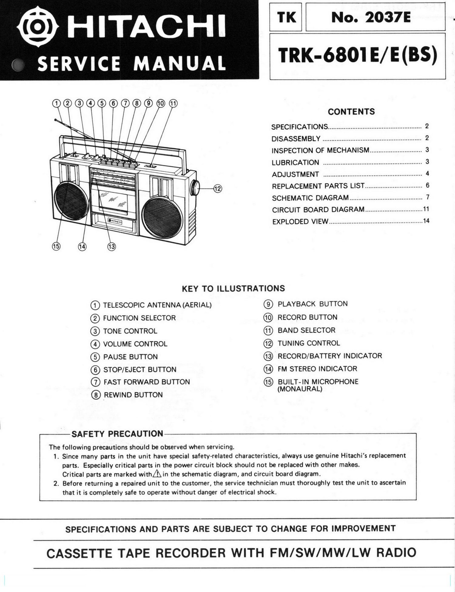
Hitachi TRK 6801 E Schematic

This is the 6 pages manual for Hitachi TRK 6801 E Schematic.
Read or download the pdf for free. If you want to contribute, please mail your pdfs to info@audioservicemanuals.com.

Page: 1 / 6
left right
Hitachi TRK 6801 E Schematic

Extracted text from Hitachi TRK 6801 E Schematic (Ocr-read)


Page 1

@ HITACHI TK No. 2037i

SERVICE MANUAL TRK"WM/El)

oeooooooOom

CONTENTS
SPECIFICATIONS ...................................................... 2
DISASSEMBLY ......................................................... 2
INSPECTION OF MECHANISM .............................. 3
LUBRICATION ......................................................... 3
ADJUSTMENT ......................................................... 4
REPLACEMENT PARTS LIST ................................. 6
SCHEMATIC DIAGRAM .......................................... 7
CIRCUIT BOARD DIAGRAM ................................. 11
EXPLODED VIEW ...................................................... 14

KEY TO ILLUSTRATIONS

Q) TELESCOPIC ANTENNA(AERIAL) C9) PLAYBACK BUTTON

@ FUNCTION SELECTOR RECORD BUTTON

® TONE CONTROL @ BAND SELECTOR

Q) VOLUME CONTROL @ TUNING CONTROL

@ PAUSE BUTTON ® RECORD/BATTERY INDICATOR

@ STOP/EJECT BUTTON FM STEREO INDICATOR

® FAST FORWARD BUTTON (5) BUILT-IN MICROPHONE
(MONAURAL)

REWIND BUTTON

-SAFETY PRECAUTION

The following precautions should be observed when servicing.
1. Since many parts in the unit have special safety-related characteristics, always use genuine Hitachi's replacement
parts. Especially critical parts in the power circuit block should not be replaced with other makes.
Critical parts are marked withAin the schematic diagram, and circuit board diagram.
2. Before returning a repaired unit to the customer, the service technician must thoroughly test the unit to ascertain
that it is completely safe to operate without danger of electrical shock.

SPECIFICATIONS AND PARTS ARE SUBJECT TO CHANGE FOR IMPROVEMENT

CASSETTE TAPE RECORDER WITH FM/SW/MW/LW RADIO