Hitachi TRK 3 D 70 Service Manual

This is the 16 pages manual for Hitachi TRK 3 D 70 Service Manual.
Read or download the pdf for free. If you want to contribute, please mail your pdfs to info@audioservicemanuals.com.

Page: 1 / 16
left right
Hitachi TRK 3 D 70 Service Manual

Extracted text from Hitachi TRK 3 D 70 Service Manual (Ocr-read)


Page 1

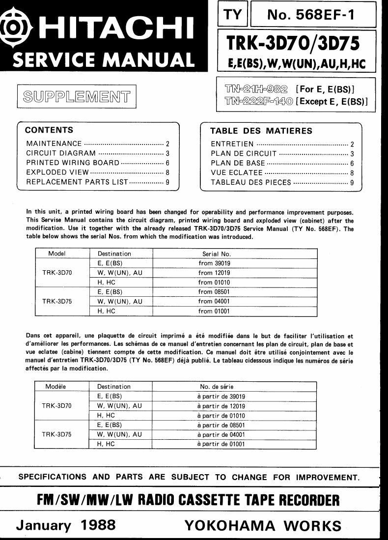
TY No. 568EF-1
TRK-3D70/3D75

E,E(BS),W,W(UN),AU,H,HC

(9) HITACHI

SERVICE MANUAL

magflnanaug [For E, E(BS)]
$UPPLEMENT TNDEZQQFDMCOD [Except E, E(BS)]
(CONTENTS TABLE DES MATIERES
MAINTENANCE ..................... ENTRETIEN .................
CIRCUIT DIAGRAM .............. PLAN DE CIRCUIT ------
PRINTED WIRING BOARD--- PLAN DE BASE ------------
EXPLODED VIEW .................. VUE ECLATEE .............
LREPLACEMENT PARTS LlST ----------------- 9 TABLEAU DES PIECES --------------------------- 9

In this unit, a printed wiring board has been changed for operability and performance improvement purposes.
This Servise Manual contains the circuit diagram, printed wiring board and exploded view (cabinet) after the
modification. Use it together with the already released TRK-3D70/3D75 Service Manual (TY No. 568EF). The
table below shows the serial Nos. from which the modification was introduced.

Model Destination Serial No.
E, E(BS) from 39019

TRK»3D70 W, W(UN), AU from 12019
H. HC from 01010

E, E(BS) from 08501

TRK-3D75 W, W(UN), AU from 04001
H, HC from 01001

Dans cet appereil, une plaquette de circuit imprimé a été modifiée dans le but de faciliter lutilisation et
daméliorer les performances. Les schémas de ce manuel dentretien concernant les plan de circuit, plan de base at
we eclatee (cabine) tiennent compte de oette modification. Ce manuel doit étre utilisé conjointement avec le
manuel d'entretien TRK-3070/3D75 (TY No. 568EF) déjé publié. Le tableau cidessous indique les numeros de série
affectés par la modification.

Models Destination No. de série
E, E(BS) é partir de 39019
TRK-3D70 W, W(UN), AU a partir de 12019
H, HC a partir de 01010
E, E(BS) é partir de 08501
TRK~3D75 W, W(UN), AU 6 partir de 04001
H, HC épartir de 01001

1 SPECIFICATIONS AND PARTS ARE SUBJECT TO CHANGE FOR IMPROVEMENT.

FM /SW/MW/I.W RADIO CASSETTE TAPE RECORDER

January 1988 YOKOHAMA WORKS

Page 2

1
1

TR K-3D70/3D75

SAFETY PRECAUTIONS

The following precautions should be observed when servicing.

1.

.N

Since many parts in the unit have special safety»related characteristics, always use genuine Hitachi's replacement
parts.

Especially critical parts in the power circuit block should not be replaced with other makers. Critical parts are
marked with A in the circuit diagram and printed wiring board.

Before returning a repaired unit to the customer, the service technician must thoroughly test the unit to ascertain
that it is completely safe to operate without danger of electrical shock.

MAINTENANCE

I Clean cabinet and panels when dirty
Clean off dirt on the surfaces with a dry cloth. Never
use thinners. benzene or alcohol since these will
damage the surface finish.

PRECAUTIONS DE SECURITE

Les precautions suivantes doivent etre observées chaque fois quune reparation doit étre faite.
1. Etant donne que de nombreux composants de lappareil possedent des caractéristiques relatives a la sécurité, utili-

ser uniquement des pieces de rechange d'origine Hitachi pour effectuer un remplacernenti Ceci se rapporte notam-
ment aux pieces critiques du bloc d'alimentation qui ne doivent en aucun cas étre remplaoées par celles d'autres
fabricants. Les pieces critiques sont aocompagnées du symbole A: dans le schéma de montage et sur la schema de
plaque de cablage.

2. Avant de retourner I'appareil réparé au client Ie technician doit proceder a un essai complet pour sassurer quil ne

présente aucun danger de chocs électriques.

ENTRETINE

I Nettoyage du coffret at des panneaux lorsqu'ils sont
sales

Enlever la poussiere des surfaces de l'appareil avec

un chiffon sec. Ne jamais utiliser de solvents, de
benzine ou d'alcool car ils abimeraient le fini des
surfaces

Check that exposed parts are acceptably insulated from
the supply circuit before returning the instrument repai- INSTRUMENT
red to the customer.

0 Checking method (Exposed part)
Power switch is set to ON.
Next, measure the resistance value between the both \
poles of attachement cup (Power supply plug) and
the input terminal (outside) of rear plate and check
that the resistance value is 500 kohms or more

-OO

Insulation tester