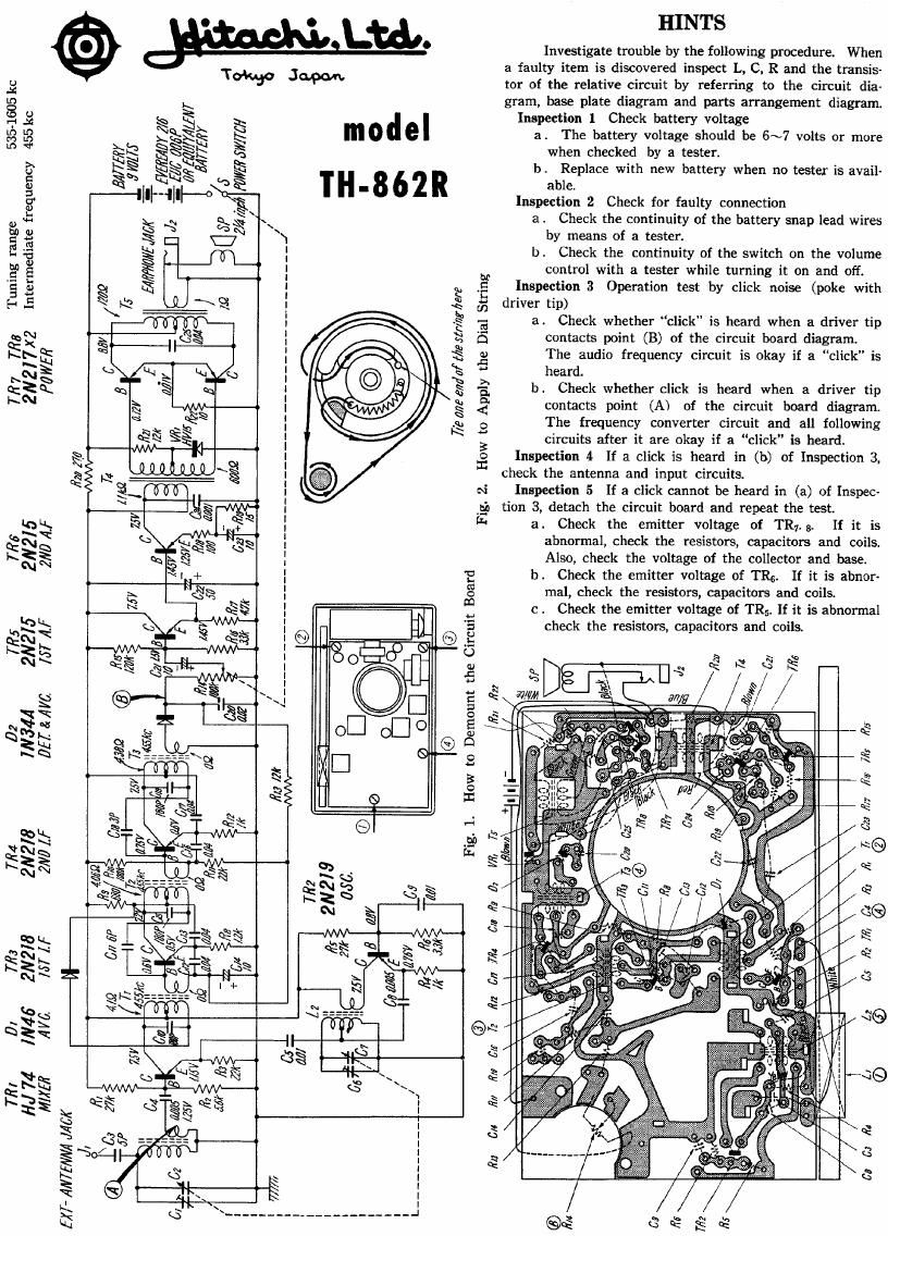
Hitachi TH 862 R Schematic 2

This is the 1 pages manual for Hitachi TH 862 R Schematic 2.
Read or download the pdf for free. If you want to contribute, please mail your pdfs to info@audioservicemanuals.com.

Page: 1 / 1
left
Hitachi TH 862 R Schematic 2

Extracted text from Hitachi TH 862 R Schematic 2 (Ocr-read)


Page 1

Intermediate frequency 455 kc

Tokyo Japan.

a l
Ln
8 s
r: K $1
Nick >~
5 es §§§§
NV N
$3 $9
-|]ll---lll

I

i=0

a

E

e

QM
x

Sufi
N
ms

522?.

RN

fiza 2M
«WV»
74
me

TIM
2N215
2W ,4 F

TR;
2N2I5
[57 AF

02
V3411
DEZ' & ,4th

I
I

/
I

_/

1. ._______________ -_....._...__.________._______-_._ -_______._

I

Tfl4
2N218
2M If

flu Mr
M

M3
[57 1F

®

model
TH-862R

[45 EN?

AM

Dz

HINTS

Investigate trouble by the following procedure. When

a faulty item is discovered inspect L, C. R and the transis-

tor of the relative circuit by referring to the circuit dia-

gram, base plate diagram and parts arrangement diagram

Inspection 1 Check battery voltage

a . The battery voltage should be 6~7 volts or more
when checked by a tester.

b. Replace with new battery when no tester is avail-

able.

Inspection 2 Check for faulty connection
a. Check the continuity of the battery snap lead wires
by means of a tester.
b. Check the continuity of the switch on the volume

driver tip)

heard.

We are mint" Me 3mm:

Fig. 2. How to Apply the Dial String

control with a tester while turning it on and off.
Inspection 3 Operation test by click noise (poke with

8. Check whether click is heard when a driver tip
contacts point (B) of the circuit board diagram.
The audio frequency circuit is okay if a click" is

1). Check whether click is heard when a driver tip
contacts point (A) of the circuit board diagram.
The frequency converter circuit and all following
circuits after it are okay if a click is heard.
Inspection 4 If a click is heard in (b) of Inspection 3,
check the antenna and input circuits.
Inspection 5 If a click cannot be heard in (a) of Inspec-
tion 3, detach the circuit board and repeat the test.
a. Check the emitter voltage of TR,. 9r

If it is

abnormal, check the resistors, capacitors and coils,
Also, check the voltage of the collector and base.

K
a
0'3 9W1 D E

/ K1]

1
/

How to Demount the Circuit Board

+
\

Fig. 1.
T:

W:
MAM/A

TI? I
HJ 74
MIMI!

EXP Ale/V/VA JACK

611 :7: 02
I

[in CH 7171
\ l \ l

C3)

fill 6'15 72

fi/I
.

6/4

[715

@
in

b. Check the emitter voltage of TR5, If it is abnor-
mal, check the resistors, capacitors and coils.

c. Check the emitter voltage of TRS. If it is abnormal
check the resistors, capacitors and coils.

e a ss
nuk-
s k ,5
§
afl/g $//
/
-, x é
,: .- c
[it/ \ 3
4 is
4
sz &e k
e
I x
Q k
s%
Sgfi i d
e
R
s l @
Q I/ Q
esse s
/ c8
S
\ : /§~
.

I
. <16
~39
Q
'5 G
#G
/
eeey...
beefiaz