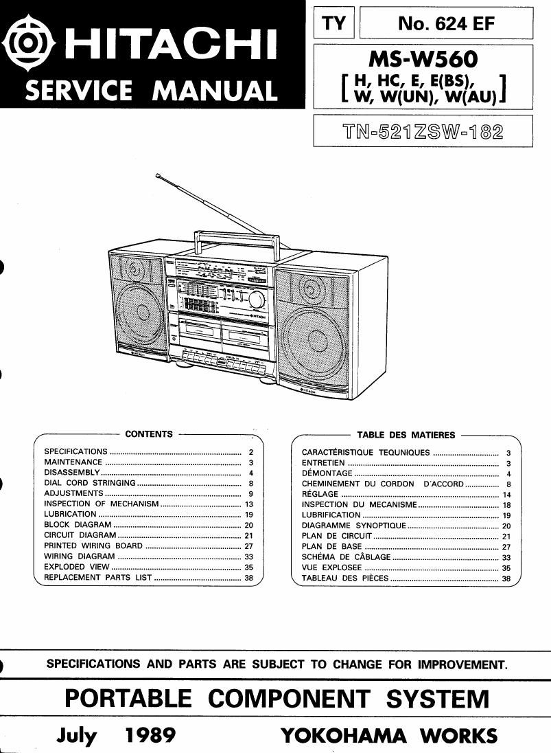
Hitachi MSW 560 Service Manual

This is the 43 pages manual for Hitachi MSW 560 Service Manual.
Read or download the pdf for free. If you want to contribute, please mail your pdfs to info@audioservicemanuals.com.

Page: 1 / 43
left right
Hitachi MSW 560 Service Manual

Extracted text from Hitachi MSW 560 Service Manual (Ocr-read)


Page 1

@HITACHI

SERVICE MANUAL

TY No. 624 EF

MS-W56O
[ H, HC, E, E(BS),
W, W(UN), W(AU)

TNESQH ZSWuI] 82

CONTENTS

SPECIFICATIONS ..............................................................
MAINTENANCE
DISASSEMBLY ......
DIAL CORD STRIN
ADJUSTMENTS ..........
INSPECTION OF MECHANISM.. ...... 13
LUBRICATION ............. 19
BLOCK DIAGRAM
CIRCUIT DIAGRAM..
PRINTED WIRING BO
WIRING DIAGRAM
EXPLODED VIEW ................... 35
REPLACEMENT PARTS LIST ......................................... 38

TABLE DES MATIERES

CARACTERISTIQUE TEQUNIQUES ............................... 3
ENTRETIEN .................................
DEMONTAGE .
CHEMINEMEN


REGLAGE ........................ 14
INSPECTION DU MECANISME .. 18
LUBRIFICATION .................................. 19

DIAGRAMME SYNOPTIOUE .....
PLAN DE cmcun....
PLAN DE BASE ......
SCHEMA DE CABLAGE
VUE EXPLOSEE .............. ..
TABLEAU DEs PIECES ................................................... as

SPECIFICATIONS AND PARTS ARE SUBJECT TO CHANGE FOR IMPROVEMENT.

PORTABLE COMPONENT SYSTEM

July 1989

YOKOHAMA WORKS

Page 2

MS-W560

SAFETY PRECAUTIONS

The following precautions should be observed when servicing.

1. Since many parts in the unit have special safety-related characteristics, always use genuine Hitachis re-
placement parts. Especially critical parts in the power circuit block should not be replaced with other makers.
Critical parts are marked with [A in the circuit diagram and printed wiring board.

2. Before returning a repaired unit to the customer, the service technician must thoroughly test the unit
to ascertain that it is completely safe to operate without danger of electrical shock.

SPECIFICATIONS

0 GENERAL

Power supply AC : 120V, 60 Hz [for H, HC]
AC :220V, 50 Hz [for E]
AC:24DV, 50 Hz [for E(BS)1
AC : 110-127/200220/230- 250V,

Power consumption
Dimensions
Weight

50/60 Hz [for W, W(UN), W(AUH
15V [IEC H20 ("D"CELL) x 10 or
equivalent]

45W

661 (W) x 265 (H) x 234 (D) mm

8.7 kg (with batteries)

DC:

' AMPLIFIER SECTION

Audio output

Spea kers

0 TUNER SECTION

Circuit system

Tuning range

80W P.M.P (AC operation)

[for E, E(BS)I

150W P.M.P (AC operation)

[for W, W(UN), W(AU)!

8W/CH (10% T.H.D. AC operation)
16cm, 49 (x2)

50m, 4.0 (x2)

FM/SW/MW/LW-4bands
superheterodyne [for E, EiBS)]
FM/SW2/SW1/MWIAMl-4bands
superheterodyne [except E, E(BS)]
FM:88 to 108 MHz [except E, E(BS)]
FM:87.5 to 108 MHZ [for E, E(BS)I
SW26 to 18 MHZ [for E, E(B$)I
SW2:7 to 22 MHz [except E, EiBS)l
SW1:2.3 to 7 MHz [except E, E(BS)]
MW(AM):530 to 1,605 kHz

LW:150 to 285 kHZ [for E, EiBSII

Intermediate

Sensitivity

Antennas

FM : 10.7MHZ

SWIMWILW :465kHz [for E, EiBSII
SW2/5W1/MWIAM) : 455kHz
[except E, EiBS)]

FM 8 LIV (S/N 26 dB)

AM (MW) 900 uV/m (S/N 20 dB)
LW 1000 uV/m (SIN 20 dB)

[for E, E(BS)I

SW 40 uV/m [for E, E(BS)I
SW2 40 pV/m
[except E, E(BS)]
SW1 300 uV/m
[except E, E(BS)]
FM SW SW2:

Telescopic antenna (aerial)
AM (MW/LW/SWI):
Ferrite core antenna

0 TAPE DECK SECTION

Tape

Tape speed

Recording system and
Bias frequency

Track system

Erasing system
Frequency Response

Signal to noise ratio
Crosstalk

Erase ratio
Motor
Wow and Flutter

Compact cassette
4.75 cm/s

AC bias, 85 kHz

4 tracks stereo

AC erase

Normal 70-12,000 Hz
Cr02 70-14,000 Hz

50 dB

Between Track 60 dB
Between Channel 40 dB
65 dB

DC motor

0.25% (WRMS)

Measured pursuant to the Federal Trade Commission's Trade
Regulation Rule on Power Claims for Amplifiers.

Check that exposed parts are acceptably insulated
from the supply circuit before returning the
instrument repaired to the customer.

- Checking method

Operate switch is set to ON.

Next, measure the resistance value between the
both poles of attachment cup (Power supply
plug) and the exposed parts (Parts such as
Knob, Cover, etc. where the customer is easy
to touch.) and check that the resistance value
is 500 kohms or more.

INSTRUMENT

(Exposed part)

\

-OO

Insulation tester (DC 500V)