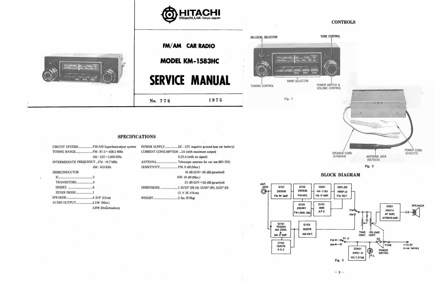
Hitachi KM 1583 HC Service Manual

This is the 6 pages manual for Hitachi KM 1583 HC Service Manual.
Read or download the pdf for free. If you want to contribute, please mail your pdfs to info@audioservicemanuals.com.

Page: 1 / 6
left right
Hitachi KM 1583 HC Service Manual

Extracted text from Hitachi KM 1583 HC Service Manual (Ocr-read)


Page 2

DISASSEMBLY

COVER HOLDING SCREW

1. Removal of cover
Remove five screws holding cover as shown in Figs 4. 5, 6 and 7. . -

\ Fig. 4

COVE R HOLDING SCREWS

Fig. 5 1* 'W_ - _v"v._'_. Fig. 9
.v \} i
I .3."- . I .
t r --"
. . O Q ~- .
. Instrument Requiered
I
I 4 7 - . Oscilloscope
COVER HOLDING SCREW ' fl-l
J ' _ Sweep Generator (Centered 10.7MH2. Sweep width i lMl-lz)
- u l , __brar '- --

' Signal Generator (FM. AM)
Fig 6 - V.T.V.M (with AC 3v or less scale)
General Preparation
1. When the radio is turned on with no signal. the voltage should
be kept in 13.2 V.
2, Turn the volume control knob fully clockwise.
NOTE : During FM-IF and FM-DISC. alignment, turn the
volume control knob to minimum.

CIRCUIT BOARD HOLDING SCREWS

R, R;

S.G®

2. Removal of circuit board

Remove two screws and lossen claw holding circuit board as .

R, :S.Gs output Impeadance

shown in Fig.8. R7 :75_ R7 (11)

Open a circuit board as shown in Fig. 9 and then repair or

F , 10
Che-Ck CIRCUIT BOARD HOLDING CLAW 'g

Fig. 8

ALIGNMENT PROCEDURE

3. During AM alignment, connect output of signal generator
(modulated by 400 or 1.000 H2 30%) to such a dummy
antenna as shown in Fig. 11,

4. During FMVRF alignment. connect output of signal generator
to such a dummy antenna as shown in Fig. 10.

5. Adjust with an insulated screw driver to prevent body effect.

6. Adjust the output of signal generator so that the reading on
the V.T.V.M may drop to minimum adjustable. as it rises
according to adjustment

7. The order of adjustment is shown below.