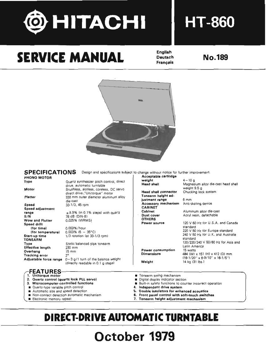
Hitachi HT 860 Service Manual

This is the 28 pages manual for Hitachi HT 860 Service Manual.
Read or download the pdf for free. If you want to contribute, please mail your pdfs to info@audioservicemanuals.com.

Page: 1 / 28
left right
Hitachi HT 860 Service Manual

Extracted text from Hitachi HT 860 Service Manual (Ocr-read)


Page 1

@ HITACHI

No.189

SERVICE MANUAL

SPECIFICATIONS Design and spécilications subject to change without notice tor lurther improwment.
PHONO MOTOR Acceptable cartilage

T t thes'zel itch control. direct 9 4- i0 9
we Exisgfaizgmatic lulpl'llabla Hand shall Magnesium alloy die-cast head shell
Motor Brushless, aimless, careless, DC servo . wa'ghl. 95 9
direct drive {'Unitorque motor Hud shall c'onnoctor Chuckmg lock system
Plotter 330 mm outer diameter aluminum alloy My "9 'd
die-cast luatmont range 6 mm
Speed 33-1/3, 45 rpm Accouorv mochantam Anti~skating device
Speed adjuurnent CABINET
'B'IBO 29.9% (in 01% steps) with quartz Cabinet Aiummurn alloy die-cast
S/N 78 dB (DlN-Bi Dust cover Acrvl resin, detachable
Wow and Flutter 002593 lWRMSl OTHERS
Spud drift Powar some: 120 V 60 Hz lor U.S.A. and Canada
(for time) 0.003%/hour standard

(Mr temperature) 0.003% (6 - 35°C)
Start-up time 1/3 rotation (at 33-1/3 rpm)

220 V 50 Hz for Europaistandard
240 V 50 Hz for LLK. and Australia

TONEAHM standard .
TV Static balanced pipe tonaarm 129/220/249 V 50/60 Hz lot Asia and
Eflectlve length 230 mm Latin America

Overhang 15 mm Power consumption 15 watts

Tracking error 2» Dimensions 484 iWi x 161 (H) x 412 (D) mm

(19-1/20 x $9/10"x16-1/5")

- 1 h I i hi
Adlustable lorca range 0 3 9/ W 0 "15 b3 3 '9 walghx 14 kg (31 lost)

(directly readable in Oli 9 steps)

FEATURES

1. Unhorquo motor

I Tonaarm swing mechanism

2. Quart: control tquart: lock PLL servo) I Digital display indicator section

3. MIcmcomputer-controlled functions I Built-in salaiy functions to counter incorrect operation
I Quartzilype variable pitch control 4. Independent drive ayatem

I Automatic size and speed detection 5. Double Emulator. {or enhancod acoustics

I Non-contact detection automatic mechanism 6. Front panel control with salt-touch switches

I Elecuomc memory repeal 7. Tonoarm insight adjustment mechanism

DIRECT-DRIVE AUTOMATIC TURNTABLE
October 1979

Page 2

HITACHI HT-860

English

SERVICE POINTS

1. Removal of mechanism assembly. DD motor.
full-auto mechanism assembly and tone arm
[Removal of mechanism assembly]

(1) Remove the five screws® and the motor cover,
and disconnect the two 10-pin connectors and
the (Spin connector.

[NOTE] Take care not to draw the rotor of the
DD motor out.

(2) Move the tone arm to near the center of the plat-
ter and then turn the unit over. Remove the 11
bottom panel setscrews and the bottom cover,
and then remove the screw. and detach the
ground wire.

(3) Remove screw© and, holding the relay P.W,B.,

disconnect the 6-pin connector.
[NOTE] With re-assembly, hold the phono cord
toward the cabinet side panel with the wiring clip
and take care not to allow the cord to touch the
mechanism assembly (leave a clearance in
the <1:- section),

(4) Remove the fool assembly (3 screws@),

(5) Remove the mechanism assembly.

Wfiflmfifi
,=/

. . .: I
3) 6*Dlll connector Q)

[Removal of DD motor]

Remove the four motor setscrews®and disconnect
the 10-pin connector and vinyl-tie.

[NOTE]

Adjustment screws can be found in locations on the
motor. If they are rotated by mistake, it will no longer
be possible to obtain the rated speed. Also, take care
that the rotor magnet is not drawn out.

Fig. 9

[Removal of full-auto mechanism assembly]

(1) Remove the three arm base setscrews © and
also the two vinyl~ties wound around the foot of
the arm base.

(2) Remove the two belts.

(3) Remove the solder on the leads from the tone
arm and sensor arm.

(4) Remove the (our main base setscrews ® and
then the main base itself.

(5) Detach the tape which anchors the leads behind
the main base.

(6) Rotate the height adjust sorew counterclockwise

and remove the full-auto mechanism assembly.
[NOTE]
Page 8 shows an instance where the full-auto
mechanism has been removed. Perform the re-
attachment of the leads, followmg the "sensor
arm and tone arm lead re-attachment"
guidelines,

PHONO lead wire
Sensor arm lead wue

Fig. 11