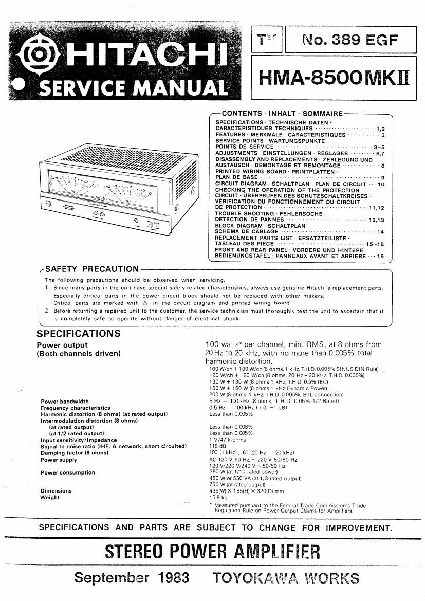
Hitachi HMA 8500 Mk2 Service Manual

This is the 15 pages manual for Hitachi HMA 8500 Mk2 Service Manual.
Read or download the pdf for free. If you want to contribute, please mail your pdfs to info@audioservicemanuals.com.

Page: 1 / 15
left right
Hitachi HMA 8500 Mk2 Service Manual

Extracted text from Hitachi HMA 8500 Mk2 Service Manual (Ocr-read)


Page 1

T17 N0. 389 EGF

HMA-SSOO MKII

z-CONTENTS- INHALT ~ /SOMMAIRE-~\
SPECIFICATIONS ' TECHNISCHE DATEN'

CARACTERISTIOUES TECHNIQUES ., 1,2
FEATURES ' MEFIKMALE - CARACTERISTIQUES 3
SERVICE POINTS- WARTUNGSPUNKTE -

POINTS DE SERVICE - , 3~5
ADJUSTMENTS ' EINSTELLUNGEN . REGLAGES .. 4- 6,7
DISASSEMBLY AND REPLACEMENTS- ZERLEGUNG UND
AUSTAUSCH . DEMONTAGE ET REMONTAGE ----------- B
PRINTED WIRING BOARD PRINTPLATTEN'

PLAN DE BASE ........................................... 9

CIRCUIT DIAGRAM - SCHALTPLAN - PLAN DE CIRCUIT 10
CHECKING THE OPERATION OF THE PROTECTION
CIRCUIT - UBERPRUFEN DES SCHUTZSCHALTKREISES'
VERIFICATION DU FONCTIONNEMENT DU CIRCUIT

DE PROTECTION . ..................................... 11,12
TROUBLE SHOOTING » FEHLERSOCHE-

DETECTION DE PANNES ------------------------------ 12,13
BLOCK DIAGRAM . SCHALTPLAN -

SCHEMA DE CABLAGE ................................... 14
REPLACEMENT PARTS LIST ERSATZTEILISTE-

TABLEAU DES p.595 ................................ 15E,

FRONT AND REAR PANEL- VORDERE UND HINTEFIE
BEDIENUNGSTAFEL- PANNEAUX AVANT ET ARHIEHE 19

J
SAFETY PRECAUTION
The following precautions should be observed when servicrng.
I. Since many parts in the unit have special safely related characteristics. always use genuine Hitachi's replacement parts.
Especially critical parts in the power circuit block should not be replaced with other makers,
Critical parts are marked with A in the circurt diagram and printed Wiring hnard
2. Before returning is repaired unit to the customer, the service technician must thoroughly test the unit to ascertain that it
IS completely safe to operate without danger of electrical shock. J

SPECIFICATIONS

Power output
(Both channels driven)

Power bandwidth
Frequency characteristics
Harmonic distortion (8 ohms) lat rated output)
Intermodulation distortion (8 ohms)
(at rated output)
(at 1/2 rated output)
Input sensitivity/Impedance
SignaI-tomoisa ratio UHF, A network. short circuited)
Damping factor (8 ohms)
Power supply

Power consumption

Dimensions
Weight

100 watts* per channel. min. RMS, at 8 ohms from
20 Hz to 20 kHz, with no more than 0.005% total

harmonic distortion.
100 W/Ch+ 100 W/Ch(8 ohms.) kHZ,T.H.D. 0,0057/oSINUS DIN Rule)
120 W/ch + 120 W/Ch (8 ohms. 20 Hz ~ 20 KHZ, T.H.D' 0.005%)
130 W +130 W (8 ohmsi KHZ, T.HD. 0.5% Him
150 W +150 W (8 ohms) kHz Dynamic Power)
200 W (8 ohms. 1 kHz. T.H.D. 0.005%. BTL connection)
5 Hz - 100 kHz (8 ohms, T.H.D. 0.05% 1/2 Rated)
0 5 Hz - 100 kHz (+0, *1 dB)
Less than 0.005%

Less than 0.008%

Less than 0.005%

I W47 k-ohms

118 dB

100 (1 kHz), 60 (20 Hz -« 20 kHz)
AC 120 V 60 Hz, ~ 220 V 50/60 Hz
120 V/220 V/24O V ~ 50/80 Hz

280 W (at V10 rated power)

450 W or 550 VA (at 113 rated output)
750 W (at rated output)

4350M x rash-1) >< 320(1)) mm

15 8 kg

' Measured pursuant to the Federal Trade Commissron's Trade
Regulation Rule on Power Output Claims for Amplifiers.

SPECIFICATIONS AND PARTS ARE SUBJECT TO CHANGE FOR IMPROVEMENT.

STEREO POWER AMPLIFIER

September 1983

TOYOKAWA WORKS