Hitachi HMA 8500 Mk2 Schematic 2

This is the 3 pages manual for Hitachi HMA 8500 Mk2 Schematic 2.
Read or download the pdf for free. If you want to contribute, please mail your pdfs to info@audioservicemanuals.com.

Page: 1 / 3
left right
Hitachi HMA 8500 Mk2 Schematic 2

Extracted text from Hitachi HMA 8500 Mk2 Schematic 2 (Ocr-read)


Page 1

ADJUSTMENTS

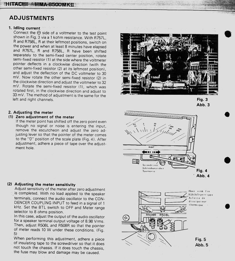
1. Idling current

Connect the 9 side of a voltmeter to the test point
shown in Fig.3 via a 1 kohm resistance. With R757L,
R and R758L, R at their leftmost positions, switch on
the power and when at least 8 minutes have elapsed
and R757L, R and R758L, R have been shifted
separately to the semi-fixed center position, rotate
semi~fixed resistor (1) at the side where the voltmeter
pointer deflects in a clockwise direction (with the
other semi»fixed resistor (2) at its leftmost position),
and adjust the deflection of the DC voltmeter to 30
mV. Now rotate the other semi-fixed resistor l2) in
the clockwise direction and adjust the voltmeter to 32
mV. Rotate the semi«fixed resistor (1), which was
rotated first, in the clockwise direction and adjust to
33 mV. The method of adjustment is the same for the
left and right channels.

2. Adjusting the meter

(1) Zero adjustment of the meter
If the meter point has shifted off the zero point even
though no signal or noise is entering the input,
remove the escutcheon and adjust the zero ad-
justing lever so that the pointer of the meter comes
to the 0" position of the scale plate (Fig. Al. After
adjustment, adhere a piece of tape over the adjust-
ment hole.

(2) Adjusting the meter sensitivity
Adjust sensitivity of the meter after zero adjustment
(is completed. With no load applied to the speaker
terminals, connect the audio oscillator to the CON-
DENCEFl COUPLlNG INPUT to feed in a signal of 1
kHz. Set the BTL switch to OFF and Meter range
selector to 8 ohms position.
In this case, adjust the output of the audio oscillator
for a speaker terminal output voltage of 8.98 Vrms.
Then, adjust R508L and RSOBR so that the pointer
of meter reads 10 W under these conditions. (Fig.
5)
When performing this adjustment, adhere a piece
of insulating tape to the screwdriver so that it does
not touch the chassis. if it does touch the chassis,
the fuse may blow and damage may be caused.

Sfltwdllvef

s hrlub n . her .
E E i c Fig. 4

Teurnzvis

His. ..nk r.n
| Kuhitnrperrtppe

Alietlc a:
l dissipateur

|i|ermlq|le .

Fig. 5
Abb. 5