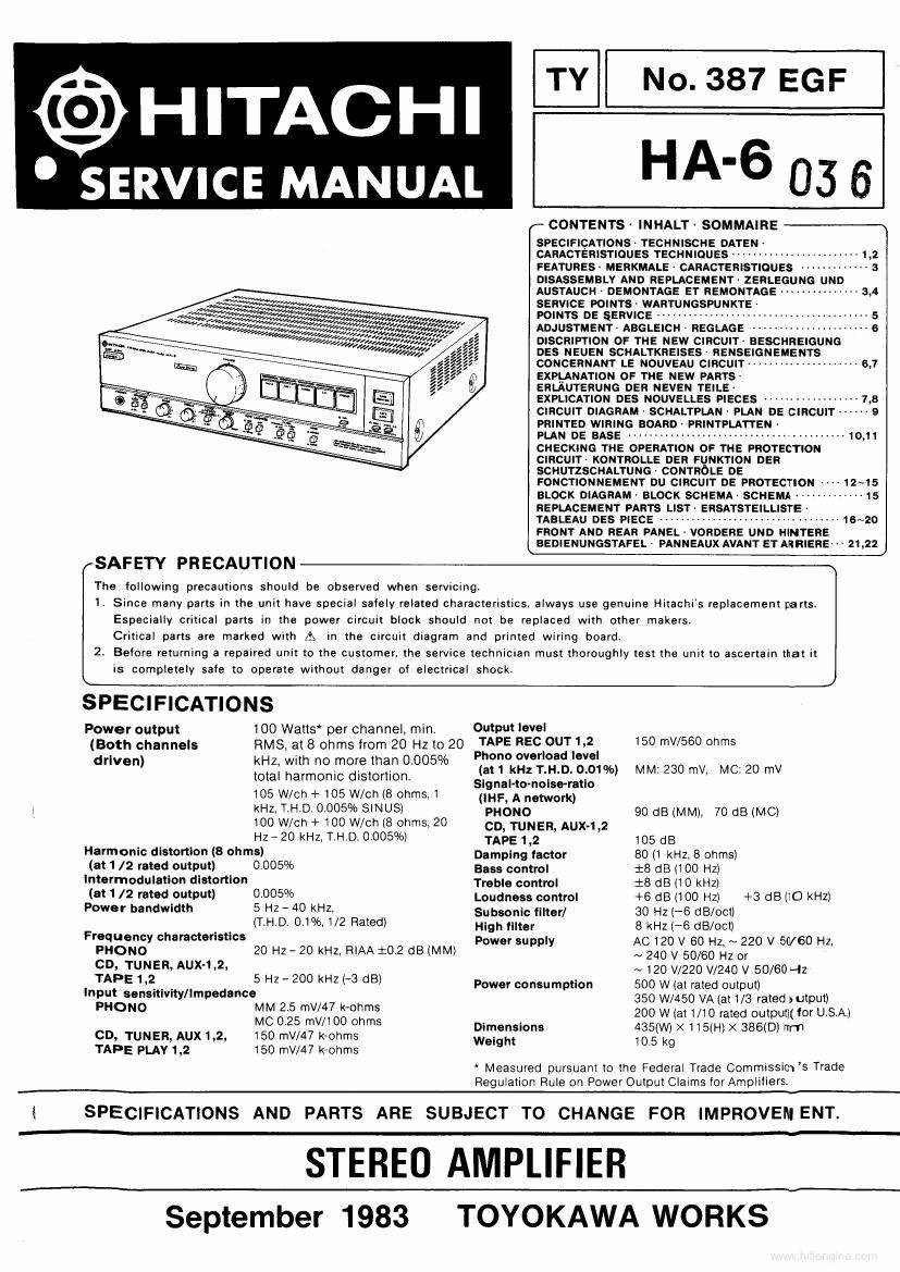
Hitachi HA 6 Service Manual

This is the 20 pages manual for Hitachi HA 6 Service Manual.
Read or download the pdf for free. If you want to contribute, please mail your pdfs to info@audioservicemanuals.com.

Page: 1 / 20
left right
Hitachi HA 6 Service Manual

Extracted text from Hitachi HA 6 Service Manual (Ocr-read)


Page 1

TY No. 387 EGF

@HITACHI

SERVICE MANUAL HA-6 03 6

r CONTENTS INHALTA SOMMAIRE
SPECIFIcATIONs- TECHNISCHE DATEN

CARACTERISTIOUES TECHNIQUES ---------------------- 1,2
FEATURESA MERKMALE - CARACTERISTIOUES ------------- a
DISASSEMBLY AND REPLACEMENT ZERLEGUNG UND

AusTAucH A DEMONTAGE ET REMONTAGE -------------- 3.4


SERVICE POINTS~ WAR
POINTS DE SERVICE ,.
ADJUSTMENT- ABGLEICH - REGLAGE ---------------------- 6
DISCRIPTION OF THE NEW CIRCUIT BESCHREIGUNG

DES NEUEN SCHALTKREISES- RENSEIGNEMENTS
CONCERNANT LE NOUVEAU CIRCUIT ----------------- 6.1
EXPLANATION OF THE NEW PARTS-

ERLAUTERUNG DER NEVEN TEILE-

MW»

. WWW», ,,
w. M,

f, Wow/WWWEMWWWmzflwmw
, w,,,;-,,,,wer~ w 0,

r fflwrev Wt/r /
/ 4w «4,, 4w, a
WWW/33:37, m r;~;v2«,,;
MmyV/I/r/

/47,


EXPLICATION DEs NOUVELLES PIECES ----------------- 7,3
CIRCUIT DIAGRAM- SCHALTPLAN PLAN DE cmculT ------ s
PRINTED WIRING BOARor PRINTPLATTEN ~

PLAN DE BASE ......................................... 10,11

CHECKING THE OPERATION OF THE PROTECTION

CIRCUIT- KONTROLLE DER FUNKTION DER
SCHUTZSCHALTUN64 CONTROLE DE

FONCTIONNEMENT DU CIRCUIT DE PROTECTION 12~15

BLOCK DIAGRAM' BLOCK SCHEMA' SCHEMA ------------- 15
REPLACEMENT PARTS LIST' ERSATSTEILLISTE -
TABLEAU DES plEcE .................................. 15~20

FRONT AND REAR PANEL * VORDERE UND HINTERE
BEDIENUNGSTAFEL- PANNEAUX AVANT ET ARHIERE- H 21,22

SAFETY PRECAUTION

The following precautions should be observed when servicingt

1. Since many parts in the unit have special safely related characteristics, always use genuine Hitachis replacement parts
Especially critical parts in the power circuit block should not be replaced with other makersr
Critical parts are marked with At In the circuit diagram and printed wiring board.

2 Before returning a repaired unit to the customer, the service technician must thoroughly test the unit to ascertain that it
is completely safe to operate without danger of electrical shock.

SPECIFICATIONS
Power output 100 Watts per channel, min, Output level
(Both channels RMS, at 8 ohms from 20 Hz to 20 PIS: :Eg'looggéfel 50 TN/560 Ohms
. - I1 V
dr've") f3; xgrrmgzi'gzlfigfiggflosoh (at 1 kHz T.H.D. 0.01 95) MM: 230 mv, MC: 20 mV
Signal-to-nolse-ratlo
105 W/cn + 105 W/ch (8 ohms 1 (INF, A network)
5 kHz, THU. 0.005% SINUSl pHONO go deal/1M), 70 (:18 (MC)
100 Mon + 100 W/ch (8 ohms, 20 CD, TUNER, AUXLZ
Hz-20 kHz. The 0.005%) TAPE 1,2 105 dB
Harmonic distortion (8 ohms) Damping (actor 80 (1 kHz. 8 ohms)
(at 1 /2 rated output) 0.005% Bass control :8 dB (100 Hz)
Intermodulation distortion Treble control :8 dB (10 kHz)
(811/2 rated output) 000% Loudness control +6 dB (100 Hz) +3 dB (:0 kHz)
Power bandwidth 5 HZ - 40 KHZ Subsonic fined 30 Hz {-6 dB/octl
(TAH-D- 01%: 2 Rated) High filter 8 kHz (A6 dB/octl
Frequency characteristics Power supply AC 120 v 60 Hz. ~ 220 v 50/60 Hz
PHONO 20 Hz- 20 kHz, RlAA :02 dB (MM) ~ 240 v 50/60 Hz or
CD. TUNER, AUX-1.2. ~ 120 V/220 V/240 v 50/60 ~Iz
TAPE 1:2. 5 HZ _ 200 kHz (3 dB) Power consumption 500 W (at rated output)
Input sensltlvlty/Impedance 350 W450 VA (at 1/3 rated output)
PHONO m" ggswcflogflrrnn: 200 w (at 1/10 rated outpullr tor U.S.A.l
, 435 X115 X3860
CD, TUNER, Aux 1,2, 150 mV/47 k-ohms $333? 105(va (H) ( mm

TAPE PLAV 1,2 150 mV/47 k-ohms

* Measured pursuant to the Federal Trade Commissicws Trade
Regulation Rule on Power Output Claims for Amplifiers.

i SPECIFICATIONS AND PARTS ARE SUBJECT TO CHANGE FOR IMPROVEMENT.

STEREO AMPLIFIER

September 1983 TOYOKAWA WORKS