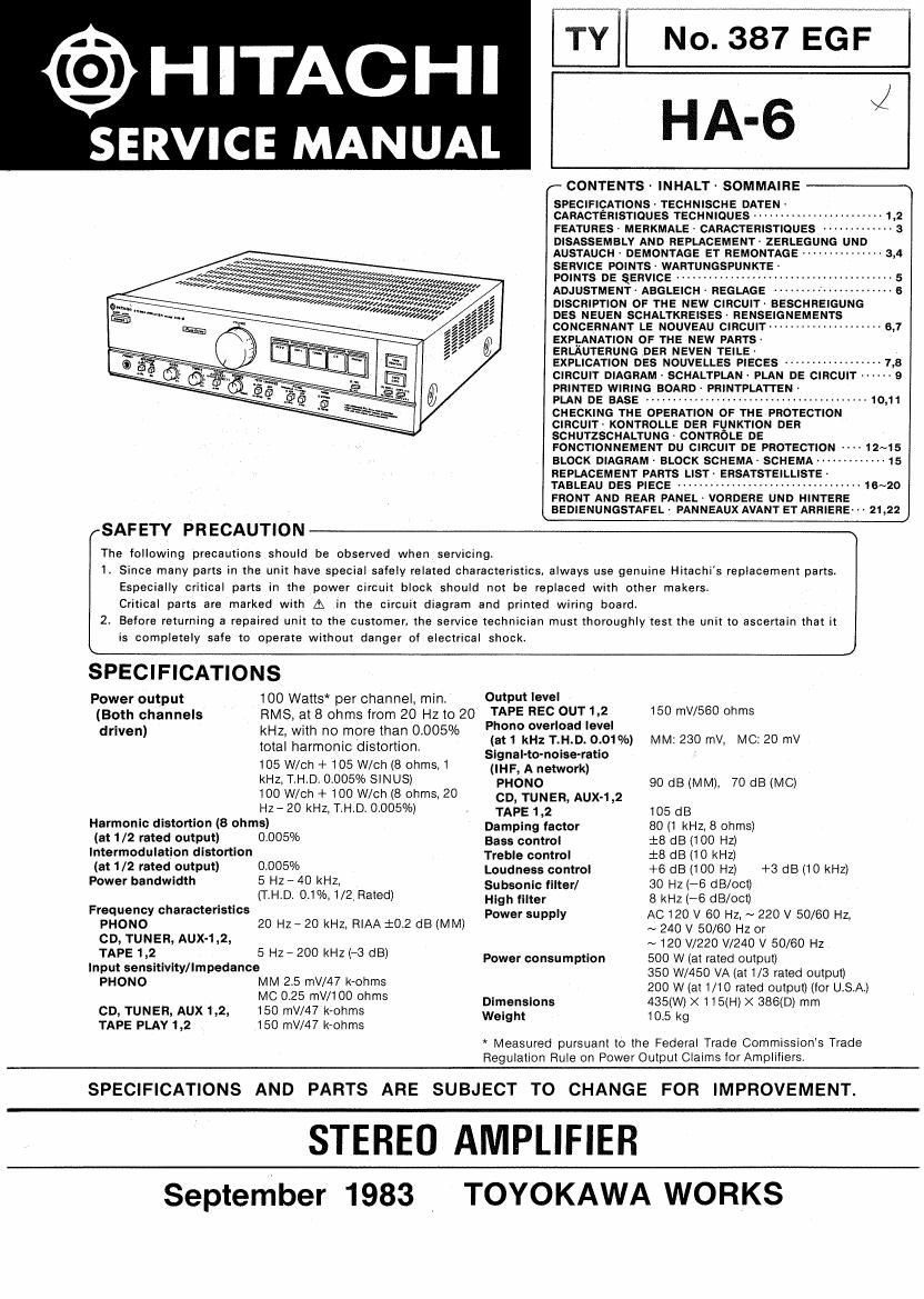
Hitachi HA 6 Schematic

This is the 2 pages manual for Hitachi HA 6 Schematic.
Read or download the pdf for free. If you want to contribute, please mail your pdfs to info@audioservicemanuals.com.

Page: 1 / 2
left right
Hitachi HA 6 Schematic

Extracted text from Hitachi HA 6 Schematic (Ocr-read)


Page 1

TY 7 No. 387 EGF

HA-6 *1

(- CONTENTS - INHALT - SOMMAIHE ---'~-\

SPECIFICATIONS~ TECHNISCHE DATEN ~
CARACTERISTIQUES TECHNIQUES ----------------
FEATURES MERKMALE ' CARACTERISTIOUES ~~~~
DISASSEMBLY AND REPLACEMENT- ZERLEGUNG UND
AUSTAUCH ' DEMONTAGE ET REMONTAGE """""""""" 3r4
SERVICE POINTS- WARTUNGSPUNKTE '

@HITACHI

SERVICE MANUAL

«4,
a, w,
Mew, «Mew W
war/rrvawizwrg

4» mm
eIfifcrrevzmeZVrgafiz,,Z;WWW/~W,,, POINTS DE ERVICE ----------------- - 5
WTZx%7w%z£zxx%% ADJUSTMENi- ABGLEICH - REGLAGE 6

«meg, Av/1, row, My 4 2,, z
4, 2», , 24,224, M , 2,, , ,
Mfltwy/rtg ix/rracx,);IWrg",,/rrr
/4? Ill/z, Wt/(u t/rl
/'/¢////////y;7/r//ll4¢;/;;Iz
kw
//

DISCRIPTION OF THE NEW CIRCUIT BESCHREIGUNG
DES NEUEN SCHALTKREISES' RENSEIGNEMENTS
CONCERNANT LE NOUVEAU CIRCUIT ------------------ 6,7
EXPLANATION OF THE NEW PARTS-

ERLAUTERUNG DER NEVEN TEILE-

EXPLICATION DES NOUVELLES PIECES --------------
CIRCUIT DIAGRAM ' SCHALTPLAN - PLAN DE CIRCUIT -
PRINTED WIRING BOARD - PRINTPLATTEN '

PLAN DE BASE ., '1 -10.11
CHECKING THE OPERATION OF THE PROTECTION
CIRCUIT' KONTROLLE DER FUNKTION DER
SCHUTZSCHALTUNG - CONTRCLE DE
FONCTIONNEMENT DU CIRCUIT DE PROTECTION
BLOCK DIAGRAM- BLOCK SCHEMA- SCHEMA
REPLACEMENT PARTS LI$T~ ERSATSTEILLISTE
TABLEAU DES PIECE .................................. 15.2.20
FRONT AND REAR PANEL- VDRDERE UND HINTERE
BEDIENUNGSTAFEL- PANNEAUX AVANT ET ARRIERE- '4 21,22


-1,3
.9

12-45
...... 15

SAFETY PR ECAUTION

The following precautions should be observed when servicing.

11 Since many parts in the unit have special safely related characteristics. always use genuine Hitachi's replacement parts.
Especially critical parts in the power circuit block should not be replaced with other makersv
Critical parts are marked with A in the circuit diagram and printed wiring board

2. Before returning a repaired unit to the customer, the service technician must thoroughly test the unit to ascertain that it
is completely safe to operate without danger of electrical shock

SPECIFICATIONS
Power output 100 Watts* per channel, min. Output level
(Both channels RMS. at 8 ohms from 20 Hz to 20 PLAPE RECIOUJILZI 150 560 Ohms
' ' 0 one over 08 eve
("we") kHZ wm 0 mole ma. 0005/ (at 1 kHz T.H.D. 0.01%) MM: 230 mv, MC: 20 mV
total harmonic distortion. SignaHo-noise-ratio ,
105 W/ch + 105 W/ch (8 ohms,1 (IHF, A network)
kHz, TiHiD, 0.005% SINUS) PHONO 90 dB (MM), 70 dB (MC)
100 W/ch + 100 W/ch (8 ohms, 20 co, TUNER, Aux-1,2
Hz - 20 kHz, T,H.Dr 0.005%) 4 TAPE 12 105 dB
Harmonic distortion (8 ohms) Damping factor 80 (1 kHz, 3 ohms)
(at 1/2 rated output) 000050/0 Bass control 1:8 dB (100 Hz)
lntermodulation distortion Treble control :8 dB (10 kHz)
(3' 1/2 tatedfulputl 0,1305% Loudness control +6 (18 (100 Hz) +3 05 (10 kHz)
90 bandw'dh 5 HZ 4° sz Subsonic filter] 30 Hz (-6 (18/000
F h t _ r (T-HD 03% 1/21 Ram) High filter 8 kHz (-6 dB/oct)
'equenwc 8'30 9"5 3 P er su I A0120 v 60 H .~ 220 v 50 60 H ,
PHONO 20 Hz- 20 kHz. RIAA i02 08 (MM) °w pp y N 240 v 50,602.42 or / Z
CD, TUNER AUX'112: 2 0 3 ~ 120 W220 V/240 v 50/60 Hz
Inzaffetiszitivity/Impedances HZ ' 0 kHz l dB) Power consumption 500 W (at rated output)
350 W/450 VA (at 1/8 rated output)
HOMO W555W17o§m§ 200 w (at 1/10 rated output) (for u.s.Ai
- ' x 11 x
CD, TUNER, AUX 1,2, 150 mV/47 kvohms 3:33:30 385$]; 5M 386(0) mm
TAPE PLAY 1.2 150 mV/47 krchms '

* Measured pursuant to the Federal Trade Commissions Trade
Regulation Rule on Power Output Claims for Amplifiers

SPECIFICATIONS AND PARTS ARE SUBJECT TO CHANGE FOR IMPROVEMENT.

STEREO AMPLIFIER
September 1983 , TOYOKAWA WORKS