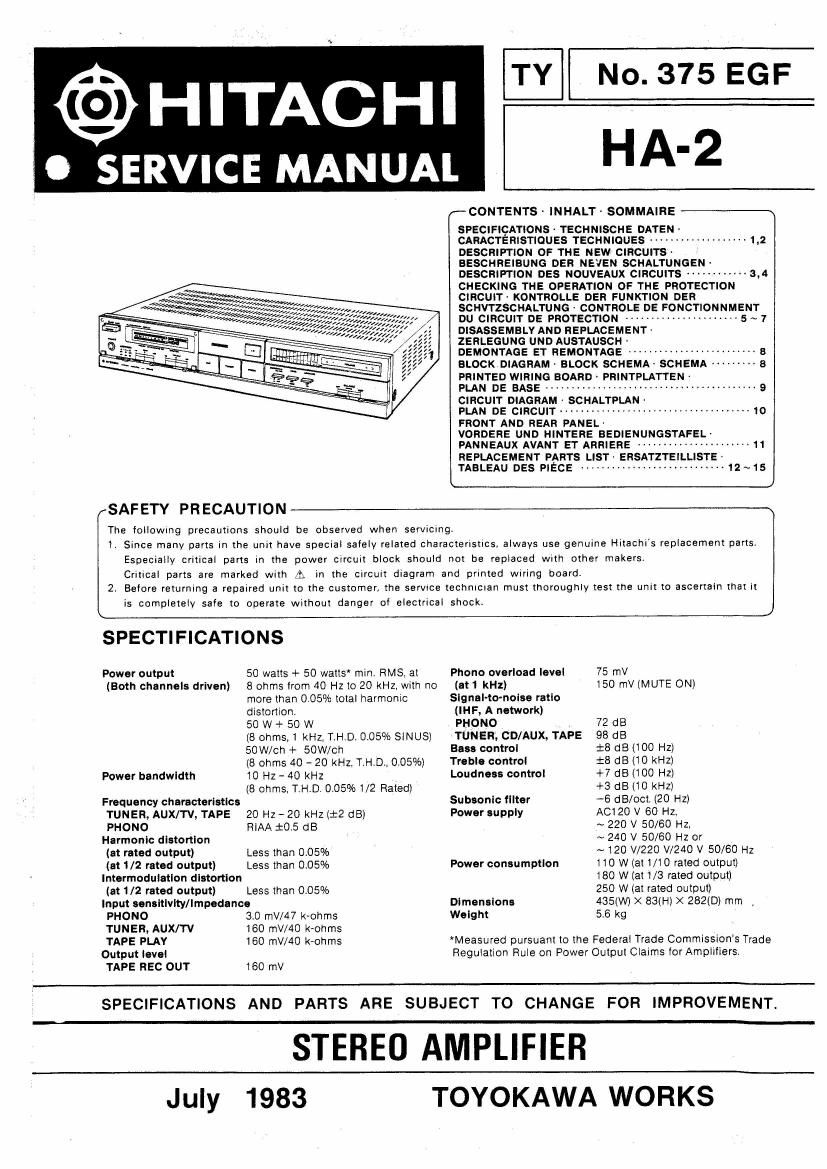
Hitachi HA 2 Service Manual

This is the 11 pages manual for Hitachi HA 2 Service Manual.
Read or download the pdf for free. If you want to contribute, please mail your pdfs to info@audioservicemanuals.com.

Page: 1 / 11
left right
Hitachi HA 2 Service Manual

Extracted text from Hitachi HA 2 Service Manual (Ocr-read)


Page 1

TY No. 375 EGF

@HITACHI

OSERVICE MANUAL HA'2

r-CONTENTS- INHALT ~ SOMMAIRE

SPECIFICATIONS- TECHNISCHE DATEN
CARACTEnIsTIOUES TECHNIQUES -m
DESCRIPTION OF THE NEw CIRCUITS-

BESCHREIBUNG OER NEVEN SCHALTUNGEN
DESCRIPTION DES NOUVEAux CIRcuth ------------ 3,4
CHECKING THE OPERATION or THE PROTECTION
CIRCUIT- KONTROLLE DER FUNKTION DER
SCHVTZSCHALTUNG - CONTROLE OE FONCTIONNMENT
DU CIRCUIT OE PROTECTION --------------------- 5 ~ 7
DISASSEMBLY ANo REPLACEMENT t

ZEHLEGUNG UND AUSTAUSCH .

DEMONTAGE ET REMONTAGE ----------------------- a
BLOCK oIAeRAM- BLOCK scuEMA» SCHEMA -------- a
PRINTED WIRING ROARo~ PRINTPLATTEN

pun DE BASE ......................................... 9
CIRCUIT D|AGRAM- SCHALTPLAN -

FLA DE CIRCUIT ..................................... ,0
FRONT AND REAR PANEL-

VOROERE UNo HINTERE BEDIENUNGSTAFELA
PANNEAUX AVANT ET ARRIERE ---------------------- 11
REPLACEMENT PARTS LIST- ERSATZTEILLISTE
LTABLEAU DES PIECE ---------------------------- 12~15

............. 132

1,:wa
:4 »/,,,./,,, 37;; 00/,
/3:, 0,, gar/WI;
//z ,;//r/,/,;; m;
12/ 2m Jar/1,
///

J

SAFETY PR ECAUTION

The followmg precautions should be observed when servicing.

1, Since many parts in the unit have special safely related characterlstlcs. always use genuine Hitachl's replacement parts
Especially critical parts in the power circuit block should not be replaced With other makersr
Critical parts are marked with A in the circuit dlagram and prInted wiring board.

2. Before returning a repaired unit to the customer, the servtce technICIan must thoroughly test the Unit to ascertain that it
is completely safe to operate without danger of electrical shock. J

SPECTIFICATIONS

Power output
(Both channels driven)

Power bandwidth

Frequency characteristics
TUNER, AUX/TV, TAPE
PHONO

Harmonic distortion
(at rated output)

(at 1/2 rated output)

Intermodulatlon distortion
(at 1/2 rated output)

50 watts + 50 watts min. HMS, at

8 ohms from 40 Hz to 20 KHz, with no
more than 0.05% total harmonic
distortion

50 W + 50 W

(8 ohms,1 kHz, T.H.D. 0.05% SINUS)
50W/ch + 50W/ch

(8 ohms 40 - 20 kHz, T,H.D., 0.05%)
10 Hz - 40 kHz

(8 Ohms, T H.D.0.05%1/2 Rated)

20 Hz ~ 20 kHz (21:2 (18)
RIAA :05 dB

Less than 0.05%
Less than 0.05%

Less than 0.0 5%

Input sensitlvlty/Impedence

PHONO
TUNER, AUX/TV
TAPE PLAY
Output level
TAPE REC OUT

30 mV/47 k~ohms
160 mV/AO k-ohms
160 mV/40 k-ohms

160 mV

Phono overload level
(at 1 kHz)
Signal-to-nolse ratio
(IHF, A network)
PHONO
TUNER; CD/AUX, TAPE
Bass control
Treble control
Loudness control

Subsonlc tllter
Power supply

Power consumptlon

Dimensions
Weight

75 rrV
150 mV (MUTE ON)

72 dB

98 dB

$8 68 (100 Hz)

:8 dB (10 kHz)

+7 (:18 (100 Hz)

+3 dB {10 kHz)

-6 dB/oct, (20 HZ)

A0120 V 60 Hz,

~ 220 V 50/60 HZ,

~ 240 V 50/60 Hz or

~ 120 V/220 W240 V 50/60 Hz
110 W (at 1/1 0 rated output)
180 W (at 1/3 rated output)
250 W (at rated output)
435(W) X 83(H) X 282(D) mm
56 kg

*Measured pursuant to the Federal Trade Commission's Trade
Regulation Rule on Power Output Claims forAmplIliers.

SPECIFICATIONS AND PARTS ARE SUBJECT TO CHANGE FOR IMPROVEMENT.

STEREO AMPLIFIER

July

1983

TOYOKAWA WORKS