Hitachi GT 5000 Service Manual

This is the 12 pages manual for Hitachi GT 5000 Service Manual.
Read or download the pdf for free. If you want to contribute, please mail your pdfs to info@audioservicemanuals.com.

Page: 1 / 12
left right
Hitachi GT 5000 Service Manual

Extracted text from Hitachi GT 5000 Service Manual (Ocr-read)


Page 1

TK No.188'IE

@ HITACHI

GT-SOOO
SERVICE MANUAL Mechanism

TECHNICAL INFORMATION

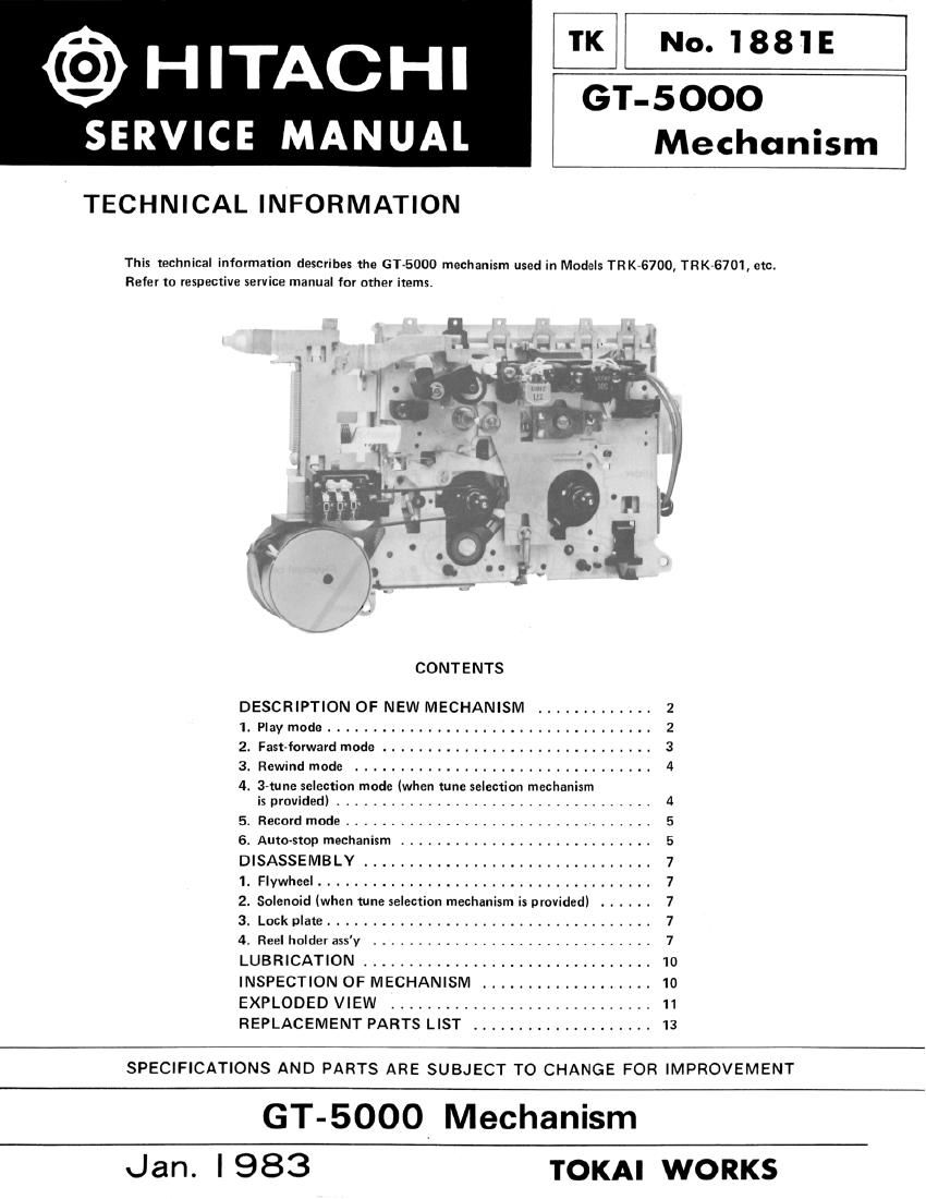
This technical information describes the GT»5000 mechanism used in Models TRK-6700, TR K-6701, etc.
Refer to respective service manual for other items.

CONTENTS

DESCRIPTION OF NEW MECHANISM ............. Z
1. Play mode .................................... Z
2. Fast-forward mode .............................. 3
3. Rewind mode ................................. 4
4. 3-tune selection mode (when tune selection mechanism

is provided) ................................... 4
5. Record mode .................................. 5
6. Auto stop mechanism ............................ 5
DISASSEMB LY ................................ 7
1. Flywheel ..................................... 7
2. Solenoid (when tune selection mechanism is provided) ...... 7
3. Lock plate .................................... 7
4. Reel holder ass'y ............................... 7
LUBRICATION ................................ 10
INSPECTION OF MECHANISM ................... 10
EXPLODED VIEW ............................. 11
REPLACEMENT PARTS LIST .................... 13

SPECIFICATIONS AND PARTS ARE SUBJECT TO CHANGE FOR IMPROVEMENT

GT-5000, Mechanism
Jan. |983 TOKAI WORKS

Page 2

GT-SOOO I

DESCRIPTION OF NEW MECHANISM

1. Play mode

When the play button is pressed, the play slider is pushed
up in the direction of arrow ® so the brake plate is
depressed to set 58 (motor switch) to ON and simulta
neously it is released from the reel and the brake is released.
The play lock arm is turned in the direction of arrow

by the projection oi the play slider and releases locking of
the play PA gear, so the play PA gear turns a little in the
direCIion of arrow and engages with the flywheel gear.
The flywheel turns in the direction of arrow @, so the
play PA gear continues to turn in the direction of arrow
and then it is locked by the play lock arm and the locking
projection of the play PA gear, and at the same time, trans-
mission of rotation by the flywheel gear is cutoff.

In the meantime, the operation arm is turned in the direc-

Play button


Play slider O
2
I 0
I t
sJ
Plav loo/it arm 6,3) x

(1)

Se lmotor switch)
.,\ (\

Play PA gear

tion of arrow © by the rotation of the operation arm
operating cam of the play PA gear, and by this, the head
plate coupled with the operation arm is depressed in the
direction of arrow @. When the head plate is depressed,
the pressure roller turns in the direction at arrow ® and is
compressed against the capstan, and at the same time the
idler is turned in the direction of arrow and is com-
pressed against the take-up real. The idler gear and the
auto-stop pulley gear are engaged with each other, and
motor rotation is transmitted to the Ilywheel, auto-stop
pulley belt, auto-stop pulley, auto-stop pulley gear, idler
gear, idler and take-up reel, and the tape is taken up in the
direction of arrow @.

Flywheel

Flywheel your

Flywhul belt
,/

Fig. 1 Play mode (initial stage)

Operation Irrn


/'
Play P3 our
Hood iii-ts

Locking protection

(,7, Connecting pert

- Operation arm operating cam

/ _, Tali-«p ml
\ Autoctop pulley bolt

Autonoo pulley

" r\\nuto¢t

, op pulley or
(\4/1 0'

Idl'r r
ldlIIr F

Fig. 2 Play mode

«2.