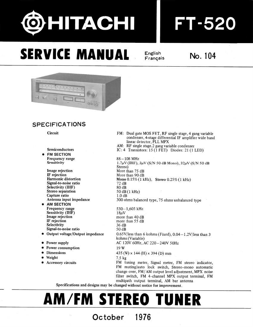
Hitachi FT 520 Service Manual

This is the 16 pages manual for Hitachi FT 520 Service Manual.
Read or download the pdf for free. If you want to contribute, please mail your pdfs to info@audioservicemanuals.com.

Page: 1 / 16
left right
Hitachi FT 520 Service Manual

Extracted text from Hitachi FT 520 Service Manual (Ocr-read)


Page 1

@HITACHI
SERVICE MANUAL

English
Frangais

No. 104

SPECIFICATIONS

Circuit

Semiconductors
FM SECTION
Frequency range
Sensitivity

Image rejection

IF rejection

Harmonic distortion
SignaHo-noise ratio
Selectivity (IHF)

Stereo separation

Capture ratio

Antenna input impedance
AM SECTION
Frequency range
Sensitivity (IHF)

Image rejection

IF rejection

Selectivity

Signal-to-noise ratio
Output voltage/ Output impedance

Power supply
Power consumption
Dimensions

Weight

Accessory circuits

FM: Dual gate MOS FET, RF single stage, 4 gang variable
condenser, 4-stage differential IF amplifier wide band
linear detector, PLL MPX

AM. RF single stage 2 gang variable condenser

1C: 4 Transistors: 15 (1 PET) Diodes: 21 (1 LED)

88 - 108 MHz

1.7;1V(IHF), 314v (S/N 50 dB Mono), 32W (S/N 50 dB
Stereo)

More than 75 dB

More than 90 dB

Mono 0.15% (1 kHz), Stereo 0.25%(1 kHz)

72 dB

80 dB

50 dB (1 kHz)

1.0 dB

300 ohms balanced type, 75 ohms unbalanced type

530~1,605 kHz

lSuV

more than 40 dB

more than 55 dB

36 dB

50 dB

0.65V/less than 6 kohms (Fixed), 0.0471.2V/less than 3
kohms (Variable)

AC 120V 60Hz, AC 220~240V 50Hz

19 W

435 (W) x 144 (H) x 394 (D) mm

7.5 kg

FM tuning meter, Signal meter, FM stereo indicator,
FM muting/auto lock switch, Stereo-mono automatic
change-over, FM / AM output level adjustment, MPX noise
filter switch, FM 4-channel MPX output terminal, FM
multipath output terminal, AM bar antenna

Specifications and designs may be changed without notice for improvement.

AM/FM STEREO TUNER

October

1976

Page 2

HITACHI

FT- 520

CARACTERISTIQUES TECHNIQUES

.0...

FEATURES

Circuit

Semi conducteur

Partie FM

Bande de fréquence

Sensibilité

Rejet image

Rejet F M

Distorsion harmonique

Rapport signal/bruit

Sélectivité (IHF)

separation stéréo

Rapport de captage

Impedance dentrée de lantenne
Partie AM

Bande de fréquence

Sensibilité (IHF)

Rejet image

Rejet F M

Sélectivite

Rapport signal/bruit

Voltage de sortie/Impedance de sortie

Alimentation
Consummation
Dimensions

Poids

Circuits Accessories

FM: MOS FET a double porte, RF a simple etage, 4
résistances variable jumeléesamplification IF a quatre
étages différentiels, détecteur linéaire de bande passante,
PLL MPX

RF syntonisé a simple étage, 2 resistances variable
jumelees

IC: 4 Transistors: 15 (1 PET) Diodes: 21 (1 LED)

AM:

88 - 108 MHz

1,7uV (IHF), 3uV (S/B 50 dB Mono), 32uV (S/N 50 dB Stéréo)
plus de 75 dB

plus de 90 dB

Mono 0,15% (1 kHz)
72 dB

80 dB

50 dB (1 kHz)

1,0 dB

type compense de 300 ohms, type non compense de 75 ohms

Stéreo 0,25% (1 kHz)

530- 1.605 kHz

ISpV

plus de 40 dB

plus de 55 dB

36 dB

50 dB

0,65 V/moins de 6 kohms (Fixes), 0,04 W 1,2 V/moins de

3 kohms (variables)

CA 120V 60 Hz, CA 220 - 240V 50 Hz

19 W

435 (L) x 144 (H) x 394 (P) mm

7,5 kg

metreur daccord FM, metreur Signal, indicateur FM stereo,
commutateur attenuateur FM/verouillage automatique,
commutateur automatique stereo/mono, reglage du niveau de
sortie FM/AM, interrupteur du filtre de bruit MPX, borne de
sortie MPX des 4 canaux FM, borne de sortie FM Multipath,
antenne ferrite AM

Les caractéristiques techniques et la presentation peuvent étre modifiées sans preavis pour des raisons

daméliorations.

The FM tuner intermediate frequency amplifier has excellent limiter characteristics because of the
use of 4-stage differential amplification with le used throughout and a 3-element ceramic filter
with excellent phase characteristics which also greatly improves selectivity. Quadrature detector
using ICs extensively makes wider bandwidth and low distortion reception possible.

The newly developed PLL (Phase Locked Loop) lC which is the result of Hitachis advanced
technology is used in the FM detector thereby achieving high separation and low distortion
combined with excellent reliability which is resistant to changes in temperature and the lapse of

time.

An auto-lock tuning mechanism is employed which makes the location of the optimum tuning

position easy in FM reception.
influences do not affect the tuning.

This mechanism eliminates tuning errors and once tuned outside

Stable reception possible with optimum separation and minimum distortion;
The use of reed relays in the FM muting circuit eliminates inter-station noise which occurs in
detuning, making listening to broadcasts more enjoyable

_2_

Page 4

HITACHI FT- 520

REPLACEMENT

1. CONTROL PRINTED WIRING BOARD

(1) Remove the meter lead wire from the Control Rmommm
printed wiring board. snowflaws

(2) Remove the six screws. (Fig. 2)

2. DIAL SCALE ILLUMINATION LAMP

(1) Remove the Lamp printed wiring board. (Fig. 3)

(2) Remove the break lamp after melting the solder of
the lead wire. (Fig. 4)

(3) A new lamp is provided for replacement. (Fig. 5)

3. FM CERAMIC FILTER
Hvi ceramic filter are classified by color-red, blue, Fi 2
orange depending on the different characteristics. 3.
Match the colors ofMF201-203. (Fig. 6) Lamp Wm WM boa,

Plaque a2 cibiage imprimguqe Jame, qeciairage ,,
4. FET (FET101I and Transistor (0101) 1...me "M N
Ferrite cores are used for the second gate ofFETlOl
and the collector of 0101. (Fig. 7)

REMPLACEMENT

1. Plaque do céhlage imprimée de commande
( 1) Désolidariser 1:) fl] dindicateur de la plaque de
ceiblage imprimée de commande.

(2) Defaire les six vis de fixation. (Fig. 2) Unsolder the connections -
Désoulez les Connexions Adheslve ("19 W'th hear)
2. Lampe d'éclairage de cadran d'accord Adhésit Ifondu avec la chaleur)
(1) Desolidariser la plaque de caiblage imprimé de lampe
déclajrage. (Fig. 3) Fig. 4 Fig. 5

(2) Retirer la lampe brisee apres dessoudage du fil
dalimentation. (Fig. 4)

(3) Une lampe neuve est fourni en vue dun remplace- Same color
merit. (Fig. 5) Méme couleur

3. Filtre céramique FM
Le filtre céramique FM est classifié a Iaide de
couleur: rouge, bleu, orange, en fonction de ses
earactéristiques.
Accorder les couleurs de MF201203. (Fig. 6)

a FET(FET101)ettmnflflor(0101) MF2°1 MF202 MF203
Les noyaux de ferrite sont employés pour a la
seconde porte de FETlOl et au niveau de lélectrode Fig 6
de captage de Q101.(Fig7) '