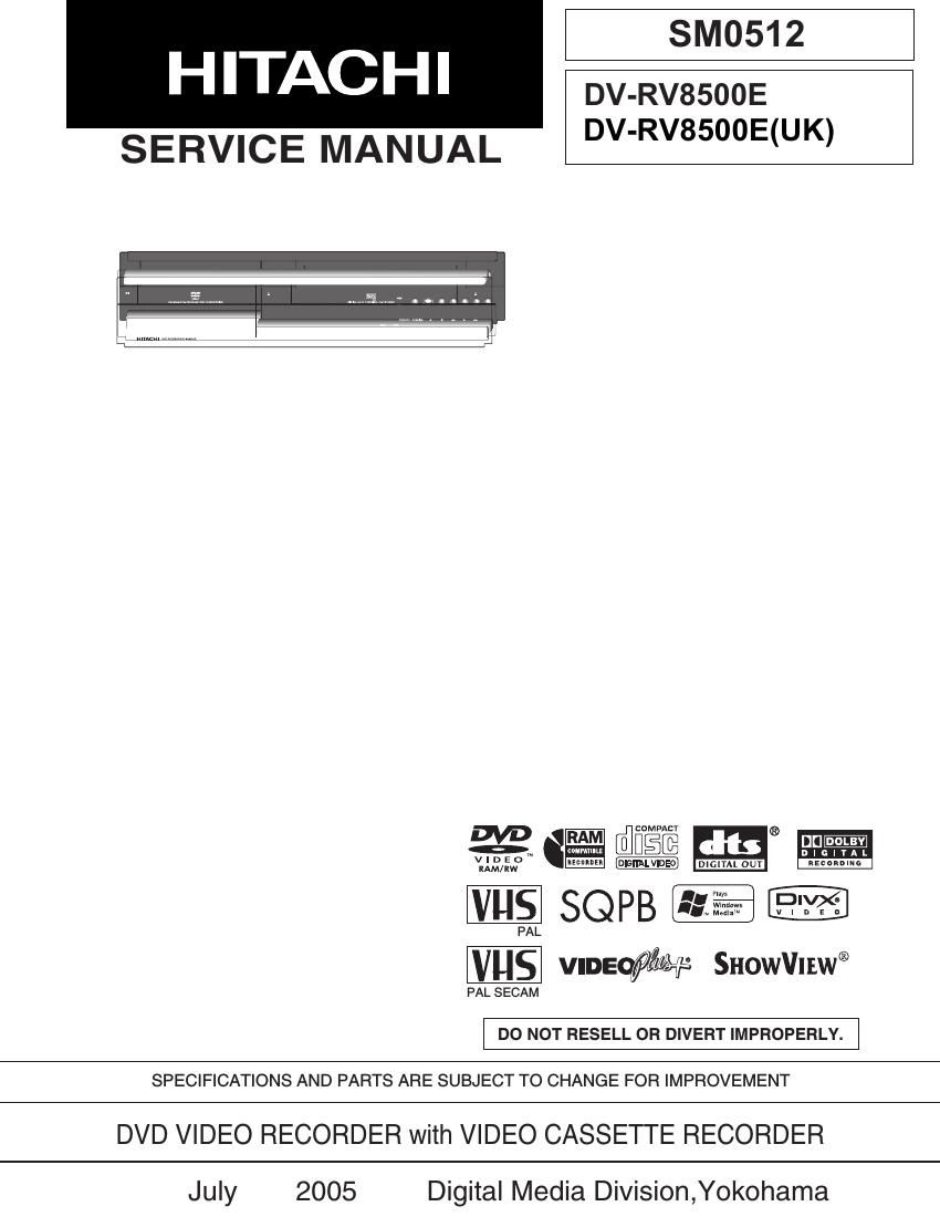
Hitachi DVRV 8500 E Service Manual

This is the 91 pages manual for Hitachi DVRV 8500 E Service Manual.
Read or download the pdf for free. If you want to contribute, please mail your pdfs to info@audioservicemanuals.com.

Page: 1 / 91
left right
Hitachi DVRV 8500 E Service Manual

Extracted text from Hitachi DVRV 8500 E Service Manual (Ocr-read)


Page 1

Contents - 1 Table of Contents 1 Safety Precaution for Repair ........... 1-1 1-1 Cautions ................................................. 1-1 1-2 Electrostatic Protecti on Measures.......... 1-2 1-3 Cautions When Hand ling DVD Drive ....... 1-2 1-4 Lead-Free Solder.................................... 1-3 1-5 Notes When Using Ser vice Manual ........ 1-4 2 General Description ......................... 2-1 2-1 Overview ................................................ 2-1 2-1-1 Service method................................... 2-1 2-1-2 Disc info rmation................................... 2-2 2-2 Features ................................................. 2-4 2-3 Specificati ons ......................................... 2-5 2-4 Major Differences from Previous Model .. 2-6 2-5 Function Differences from Previous M odel ....................................... 2-7 2-6 Names of Parts ....................................... 2-8 2-7 List of Abbreviations and Te rms for DVD Recorder ............................................... 2-12 3 Details of Servicing and Troubleshooting ............................... 3-1 3-1 Details of Servicing................................. 3-1 3-1-1 Removing Disc from Faulty Recorder ... 3-1 3-1-2 Removing Video Cassette from Faulty Recorder ............................................... 3-1 3-1-3 Firm ware .............................................. 3-2 3-1-4 Setting to defaults at the factory ........... 3-3 3-2 Troubleshoo ting ...................................... 3-4 3-2-1 Troubleshooting electronic system ........3-4 3-2-2 Troubleshooting m echanical block ...... 3-14 4 Disassembly and Reassembly ........ 4-1 4-1 Order of Disassembly............................. 4-1 4-2 Cabinet Di sassembly.............................. 4-1 (1) Top Cove r ................................................. 4-1 (2) Front Panel ............................................... 4-2 (3) FAN M otor ................................................ 4-2 (4) SMPS P.C. B ............................................. 4-3 (5) Deck m echanism ...................................... 4-4 (6) TIMER P. C.B ............................................ 4-5 (7) VCR P.C. B ................................................ 4-5 (8) DVD multi-drive ........................................ 4-6 (9) VDR, JACK and KEY P.C.Bs.................... 4-6 4-3 Deck Mechanism Parts Locations........... 4-7 4-4 Deck Mechanism Disassembly................ 4-8 (1) Drum assembly ........................................ 4-8 (2) Top pl ate ................................................... 4-9 (3) CST holder a ssembly............................... 4-9 (4) F/L rack gear assembly............................ 4-9 (5) Door opener............................................. 4-9 (6) F/L arm assem bly ..................................... 4-9 (7) S/W lever assembly.................................. 4-9 (8) L/D motor assembly............................... 4-11 (9) Wheel gear ............................................. 4-11 (10) F/E head .............................................. 4-11 (11) A/C head assem bly .............................. 4-11 (12) T brake assembly................................. 4-12 (13) Tension arm assembly.......................... 4-12 (14) S reel and T reel ................................... 4-12 (15) P4 base assembly................................ 4-13 (16) Lid opener............................................ 4-13 (17) Pressure arm assem bly ....................... 4-13 (18) Take-up ar m ......................................... 4-13 (19) Capstan s upporter............................... 4-14 (20) Capstan belt and capstan motor ........... 4-14 (21) F/R leve r ............................................... 4-14 (22) D37 clutch assembly............................ 4-14 (23) Driver gear and cam gear..................... 4-15 (24) Sector gear ................. ......................... 4-15 (25) Capstan brake assembly...................... 4-15 (26) Slider plate ........................................... 4-15 (27) Tension lever ........................................ 4-15 (28) Spring lever ................. ......................... 4-15 (29) Brake le ver ........................................... 4-15 (30) P2 gear assembly and P3 gear assembl y ................................. 4-16 (31) P2 base assembly and P3 base assembl y ................................ 4-16 (32) Loading base ................ ........................ 4-16 (33) Tension base ................. ....................... 4-17 (34) Jog idler ar m assembly........................ 4-17 4-5 Checking Mode after Reassembling Deck Mechanism ........................................... 4-18

Page 2

Contents - 2 5 Adjustment / Maintenance ............... 5-1 5-1 Set-up for Adjustment ............................. 5-1 5-2 VCR Electrical Adjustment..................... 5-2 5-2-1 Head switching adjustment................... 5-2 5-3 Deck Mechanism Tape Transport System Adjustment ............................................. 5-3 5-3-1 Guide roller height adjustment ................. 5-3 5-3-2 A/C head adjustment............................ 5-4 5-3-3 X-value adj ustment............................... 5-5 5-3-4 Adjustments after replacing drum assem bly ..................................... 5-5 5-3-5 Check after adjustment........................ 5-6 5-3-6 Method of setting the mechanism to loading status without inserting tape ..... 5-6 5-3-7 Reel torques ......................................... 5-7 5-4 Maintenance ............................................ 5-8 5-4-1 Maintenance and inspection ................. 5-8 5-4-2 Lubricating o il and greasing ................ 5-10 6 Exploded View and Parts List.......... 6-1 6-1 Exploded Views ...................................... 6-1 6-1-1 Cabinet S ection................................... 6-1 6-1-2 F / L Mechanism .................................. 6-2 6-1-3 Deck Mechanism Section - Top view ... 6-3 6-1-4 Deck Mechanism Section - Bottom view 6-4 6-2 Parts List ................................................. 6-5 6-2-1 Mechanical Parts List ........................... 6-5 6-2-2 Electrical Parts List ............................... 6-6 S Schematic, Wiring Diagrams .......... S-1 S-1 Wiring Diag ram ....................................... S-1 S-2 S.M.P.S Schem atic Diagram ................... S-2 S-3 SYSTEM Schematic Diagram(VCR P.C.B) S-3 S-4 TUNER Schematic Diagram(VCR P.C.B) .. S-4 S-5 A/V Schematic Diag ram(VCR P.C.B) ...... S-5 S-6 Hi-Fi Schematic Diagram(VCR P.C.B) .... S-6 S-7 REAR JACK Schematic Diagram (VCR P.C. B) ............................................ S-7 S-8 TIMER,KEY Schematic Diagrams .......... S-8 S-9 JACK Schematic Diagram...................... S-9 S-10 A/V,SYSTEM Circuit Wa veforms ......... S-10 S-11 CIRCUIT VOLT AGE CHART................ S-11 C Circuit Board Diagrams .................. C-1 C-1 VCR Circuit Boar d Diagram ................... C-1 C-2 S.M.P.S Circuit Board Diagram .............. C-3 C-3 JACK Circuit Board Diagram ................. C-4 C-4 TIMER Circuit Board Diagram ............... C-4 C-5 KEY Circuit Board Diagram................... C-4 B Block Diagrams ............................... B-1 B-1 S.M.P.S Circuit Block Diagram ................ B-1 B-2 VIDEO Circuit Bloc k Diagram ................. B-2 B-3 AUDIO Circuit Bloc k Diagram ................. B-3 B-4 SYSTEM Circuit Block Diagram.............. B-4 B-5 VIDEO I/O Circuit Block Diagram ........... B-5