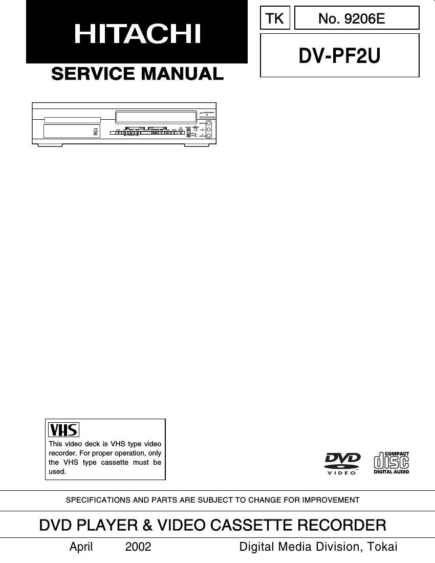
Hitachi DVPF 2 U Service Manual

This is the 97 pages manual for Hitachi DVPF 2 U Service Manual.
Read or download the pdf for free. If you want to contribute, please mail your pdfs to info@audioservicemanuals.com.

Page: 1 / 97
left right
Hitachi DVPF 2 U Service Manual

Extracted text from Hitachi DVPF 2 U Service Manual (Ocr-read)


Page 1

CONTENTS SPECIFICATIONS. . . . . . . . . . . . . . . . . . . . . . . . . . . . . 1-1-1 COMPARISON OF MODELS . . . . . . . . . . . . . . . . . . . . 1-2-1 LASER BEAM SAFETY PRECAUTIONS. . . . . . . . . . . 1-3-1 IMPORTANT SAFETY PRECAUTIONS. . . . . . . . . . . . 1-4-1 Product Safety Notice . . . . . . . . . . . . . . . . . . . . . . . . . 1-4-1 Precautions during Servicing . . . . . . . . . . . . . . . . . . . . 1-4-1 Safety Check after Servicing . . . . . . . . . . . . . . . . . . . . 1-4-2 STANDARD NOTES FOR SERVICING . . . . . . . . . . . . 1-5-1 Circuit Board Indications . . . . . . . . . . . . . . . . . . . . . . . 1-5-1 Instructions for Connectors . . . . . . . . . . . . . . . . . . . . . 1-5-1 How to Remove/Install Flat Pack-IC . . . . . . . . . . . . . . 1-5-1 Instructions for Handling Semi-conductors . . . . . . . . . 1-5-3 PREPARATION FOR SERVICING. . . . . . . . . . . . . . . . 1-6-1 How to Enter the Service Mode . . . . . . . . . . . . . . . . . . 1-6-1 ORERATING CONTROLS AND FUNCTIONS. . . . . . . 1-7-1 FIRMWARE RENEWAL MODE . . . . . . . . . . . . . . . . . . 1-8-1 TROUBLESHOOTING . . . . . . . . . . . . . . . . . . . . . . . . . 1-9-1 CABINET DISASSEMBLY INSTRUCTIONS . . . . . . . . 2-1-1 1. Disassembly Flowchart . . . . . . . . . . . . . . . . . . . . . . 2-1-1 2. Disassembly Method . . . . . . . . . . . . . . . . . . . . . . . . 2-1-1 DISASSEMBLY/ASSEMBLY PROCEDURES OF DECK MECHANISM. . . . . . . . . . . . . . . . . . . . . . . . . . 2-2-1 ALIGNMENT PROCEDURES OF MECHANISM . . . . . 2-3-1 ELECTRICAL ADJUSTMENT INSTRUCTIONS . . . . . 2-4-1 Test Equipment Required . . . . . . . . . . . . . . . . . . . . . . 2-4-1 Head Switching Position Adjustment . . . . . . . . . . . . . . 2-4-1 FIXTURE AND TAPE FOR ADJUSTMENT . . . . . . . . . 2-5-1 How to Use The Fixtures . . . . . . . . . . . . . . . . . . . . . . . 2-5-1 MECHANICAL ALIGNMENT PROCEDURES . . . . . . . 2-6-1 Service Information . . . . . . . . . . . . . . . . . . . . . . . . . . . 2-6-1 1. Tape Interchangeability Alignment . . . . . . . . . . . . . . 2-6-2 1-A.Preliminary/Final Checking and Alignment of Tape Path . . . . . . . . . . . . . . . . . . . 2-6-3 1-B.X Value Alignment . . . . . . . . . . . . . . . . . . . . . . . . 2-6-3 1-C.Checking/Adjustment of Envelope Waveform . . . 2-6-4 1-D.Azimuth Alignment of Audio/Control/Erase Head . . . . . . . . . . . . . . . . . 2-6-4 STANDARD MAINTENANCE. . . . . . . . . . . . . . . . . . . . 2-7-1 Service Schedule Components . . . . . . . . . . . . . . . . . . 2-7-1 Cleaning . . . . . . . . . . . . . . . . . . . . . . . . . . . . . . . . . . . 2-7-2 EXPLODED VIEWS . . . . . . . . . . . . . . . . . . . . . . . . . . . 3-1-1 Cabinet . . . . . . . . . . . . . . . . . . . . . . . . . . . . . . . . . . . . 3-1-1 Deck Mechanism View 1 . . . . . . . . . . . . . . . . . . . . . . . 3-1-2 Deck Mechanism View 2 . . . . . . . . . . . . . . . . . . . . . . . 3-1-2 Deck Mechanism View 3 . . . . . . . . . . . . . . . . . . . . . . . 3-1-3 REPLACEMENT PARTS LIST. . . . . . . . . . . . . . . . . . . 3-2-1 Mechanical Parts List . . . . . . . . . . . . . . . . . . . . . . . . . 3-2-1 Electrical Parts List . . . . . . . . . . . . . . . . . . . . . . . . . . . 3-2-3SCHEMATIC DIAGRAMS/CBAS AND TEST POINTS. . . . . . . . . . . . . . . . . . . . . . . . . . . . . . . 4-1-1 Wiring Diagram . . . . . . . . . . . . . . . . . . . . . . . . . . . . . . 4-1-3 Main 1/5 Schematic Diagram . . . . . . . . . . . . . . . . . . . 4-1-4 Main 2/5 Schematic Diagram . . . . . . . . . . . . . . . . . . . 4-1-5 Main 3/5 Schematic Diagram . . . . . . . . . . . . . . . . . . . 4-1-6 Main 4/5 Schematic Diagram . . . . . . . . . . . . . . . . . . . 4-1-7 Main 5/5 Schematic Diagram . . . . . . . . . . . . . . . . . . . 4-1-8 Waveforms . . . . . . . . . . . . . . . . . . . . . . . . . . . . . . . . . 4-1-9 Function Schematic Diagram . . . . . . . . . . . . . . . . . . 4-1-10 Jack Schematic Diagram. . . . . . . . . . . . . . . . . . . . . . 4-1-11 Main CBA Top View . . . . . . . . . . . . . . . . . . . . . . . . . 4-1-12 Main CBA Bottom View . . . . . . . . . . . . . . . . . . . . . . . 4-1-13 Function CBA Top/Bottom View . . . . . . . . . . . . . . . . 4-1-14 Jack CBA Top/Bottom View . . . . . . . . . . . . . . . . . . . 4-1-15 Wiring Diagram . . . . . . . . . . . . . . . . . . . . . . . . . . . . . 4-1-16 DVD Main 1/4 Schematic Diagram . . . . . . . . . . . . . . 4-1-17 DVD Main 2/4 Schematic Diagram . . . . . . . . . . . . . . 4-1-18 DVD Main 3/4 Schematic Diagram . . . . . . . . . . . . . . 4-1-19 DVD Main 4/4 Schematic Diagram . . . . . . . . . . . . . . 4-1-20 BLOCK DIAGRAMS. . . . . . . . . . . . . . . . . . . . . . . . . . . 4-2-1 [ VTR Section ] Servo/System Control Block Diagram . . . . . . . . . . . . . 4-2-1 Video Block Diagram . . . . . . . . . . . . . . . . . . . . . . . . . . 4-2-2 Audio Block Diagram . . . . . . . . . . . . . . . . . . . . . . . . . . 4-2-3 Hi-Fi Audio Block Diagram . . . . . . . . . . . . . . . . . . . . . 4-2-4 Power Supply Block Diagram . . . . . . . . . . . . . . . . . . . 4-2-5 [ DVD Section ] DVD System Control Block Diagram . . . . . . . . . . . . . . 4-2-6 RF Signal Control/Servo Block Diagram . . . . . . . . . . . 4-2-7 DVD Signal Process Block Diagram . . . . . . . . . . . . . . 4-2-8 DVD Video Block Diagram . . . . . . . . . . . . . . . . . . . . . 4-2-9 DVD Audio Block Diagram . . . . . . . . . . . . . . . . . . . . 4-2-10 SYSTEM CONTROL TIMING CHARTS. . . . . . . . . . . . 4-3-1 IC PIN FUNCTION DESCRIPTIONS . . . . . . . . . . . . . . 4-4-1 LEAD IDENTIFICATIONS. . . . . . . . . . . . . . . . . . . . . . . 4-5-1 CHAPTER 1 GENERAL INFORMATION CHAPTER 2 DISASSEMBLY AND ADJUSTMENT CHAPTER 3 EXPLODED VIEWS AND PARTS LIST CHAPTER 4SCHEMATIC AND BLOCK DIAGRAMS/ CBAS

Page 2

1-1-1 Product type: DVD player with Video Cassette Recorder Discs & Tapes: DVD video Audio CD VHS Video Cassette tape Converter output: VHF Channel 3 or 4. Power source: 120 V AC +/- 10%, 60 Hz +/- 0.5% Power consumption: 25 W (standby: 7.2 W) Operating temperature: 5˚ C to 40˚C Dimensions: W 17-1/8 (435 mm) H 4 (99 mm) D 10-1/2 (266 mm) Weight: 8.8 lbs (4 kg) SPECIFICATIONS Manufactured under license from Dolby Laboratories. "Dolby" and the double-D symbol are trademarks of Dolby Laboratories. "DTS" and "DTS Digital Out" are trademarks of Digital Theater Systems Inc. CHAPTER 1 GENERAL INFORMATION

Page 17

1-8-1 FIRMWARE RENEWAL MODE HOW TO UPDATE THE FIRMWARE VERSION 1. Turn the power on and remove the disc on the tray. 2. To put the DVD player into version up mode, press[9], [8], [7], [6], and [SEARCH MODE] buttons on the remote control unit in that order. The tray will open automatically. Fig. a appears on the screen and Fig. b appears on the VFD. The DVD player can also enter the version up mode with the tray open. In this case, Fig. a will be shown on the screen while the tray is open. 3. Load the disc for version up. (For closing the tray, only the "OPEN/CLOSE" button is available.) 4. The DVD player enters the F/W version up mode automatically. Fig. c appears on the screen and Fig. d appears on the VFD. The appearance shown in (*2) of Fig. c is described as follows: 5. After programming is finished, the tray opens auto- matically. Fig. e appears on the screen and the checksum in (*3) of Fig. e appears on the VFD. (Fig. f) At this time, no buttons are available. 6. For tray opening, plug the AC cord into the AC out- let. 7. Turn the power on by pressing the power button and the tray will close. HOW TO VERIFY THE FIRMWARE VERSION 1. After making sure that no disc is in unit, turn thepower on. 2. Press [1], [2], [3], [4], and [DISPLAY] buttons on the remote control unit in that order. The B/E ver- sion appears on the VFD, and the F/E and B/E ver- sions appear on TV screen. BE F/W VERSION UP MODE PLEASE INSERT A DISC FOR BE F/W VERSION UP. EXIT: POWER Fig. a Version Up Mode Screen Fig. b VFD in Version Up Mode BE F/W VERSION UP MODE VERSION:******** Reading...(*2) Fig. c Programming Mode Screen Fig. d VFD in Programming Mode (Example) Appearance No. State Reading... Sending files into the memory Erasing... Erasing previous version data Programming... 1 2 3 Writing new version data BE F/W VERSION UP MODE VERSION: ******** COMPLETED SUM:7abc(*3) Fig. e Completed Program Mode Screen Fig. f VFD upon Finishing the Programing Mode (Example)