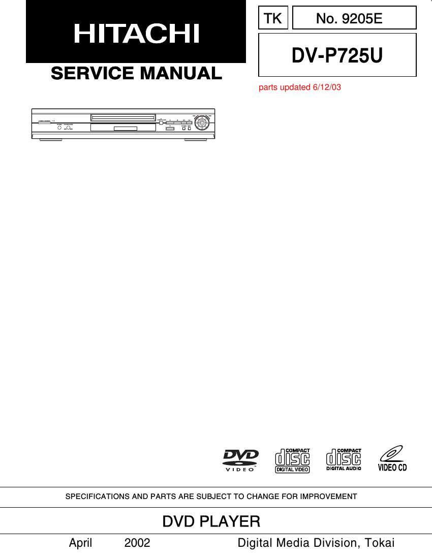
Hitachi DVP 725 U Service Manual

This is the 57 pages manual for Hitachi DVP 725 U Service Manual.
Read or download the pdf for free. If you want to contribute, please mail your pdfs to info@audioservicemanuals.com.

Page: 1 / 57
left right
Hitachi DVP 725 U Service Manual

Extracted text from Hitachi DVP 725 U Service Manual (Ocr-read)


Page 1

CONTENTS SPECIFICATIONS. . . . . . . . . . . . . . . . . . . . . . . . . . . . . 1-1-1 COMPARISON OF MODELS . . . . . . . . . . . . . . . . . . . . 1-2-1 LASER BEAM SAFETY PRECAUTIONS. . . . . . . . . . . 1-3-1 IMPORTANT SAFETY PRECAUTIONS. . . . . . . . . . . . 1-4-1 Product Safety Notice . . . . . . . . . . . . . . . . . . . . . . . . . 1-4-1 Precautions during Servicing . . . . . . . . . . . . . . . . . . . . 1-4-1 Safety Check after Servicing . . . . . . . . . . . . . . . . . . . . 1-4-2 STANDARD NOTES FOR SERVICING . . . . . . . . . . . . 1-5-1 Circuit Board Indications . . . . . . . . . . . . . . . . . . . . . . . 1-5-1 Instructions for Connectors . . . . . . . . . . . . . . . . . . . . . 1-5-1 How to Remove/Install Flat Pack-IC . . . . . . . . . . . . . . 1-5-1 Instructions for Handling Semi-conductors . . . . . . . . . 1-5-3 ORERATING CONTROLS AND FUNCTIONS. . . . . . . 1-6-1 FIRMWARE RENEWAL MODE . . . . . . . . . . . . . . . . . . 1-7-1 TROUBLESHOOTING . . . . . . . . . . . . . . . . . . . . . . . . . 1-8-1 CABINET DISASSEMBLY INSTRUCTIONS . . . . . . . . 2-1-1 1. Disassembly Flowchart . . . . . . . . . . . . . . . . . . . . . . 2-1-1 2. Disassembly Method . . . . . . . . . . . . . . . . . . . . . . . . 2-1-1 EXPLODED VIEWS . . . . . . . . . . . . . . . . . . . . . . . . . . . 3-1-1 Cabinet . . . . . . . . . . . . . . . . . . . . . . . . . . . . . . . . . . . . 3-1-1 REPLACEMENT PARTS LIST. . . . . . . . . . . . . . . . . . . 3-2-1 Mechanical Parts List . . . . . . . . . . . . . . . . . . . . . . . . . 3-2-1 Electrical Parts List . . . . . . . . . . . . . . . . . . . . . . . . . . . 3-2-2SCHEMATIC DIAGRAMS/CBAS AND TEST POINTS. . . . . . . . . . . . . . . . . . . . . . . . . . . . . . . 4-1-1 Wiring Diagram . . . . . . . . . . . . . . . . . . . . . . . . . . . . . . 4-1-3 DVD Main 1/4 Schematic Diagram . . . . . . . . . . . . . . . 4-1-4 DVD Main 2/4 Schematic Diagram . . . . . . . . . . . . . . . 4-1-5 DVD Main 3/4 Schematic Diagram . . . . . . . . . . . . . . . 4-1-6 DVD Main 4/4 Schematic Diagram . . . . . . . . . . . . . . . 4-1-7 AV 1/3 Schematic Diagram . . . . . . . . . . . . . . . . . . . . . 4-1-8 AV 2/3 & Headphone Schematic Diagram . . . . . . . . . 4-1-9 Waveforms . . . . . . . . . . . . . . . . . . . . . . . . . . . . . . . . 4-1-10 AV 3/3, Function & Switch Schematic Diagram . . . . 4-1-11 Progressive Schematic Diagram . . . . . . . . . . . . . . . . 4-1-12 Function CBA Top View . . . . . . . . . . . . . . . . . . . . . . 4-1-13 Function CBA Bottom View . . . . . . . . . . . . . . . . . . . . 4-1-13 Headphone CBA Top View . . . . . . . . . . . . . . . . . . . . 4-1-13 Headphone CBA Bottom View . . . . . . . . . . . . . . . . . 4-1-13 AV CBA Top View . . . . . . . . . . . . . . . . . . . . . . . . . . . 4-1-14 AV CBA Bottom View . . . . . . . . . . . . . . . . . . . . . . . . 4-1-15 Switch CBA Top View . . . . . . . . . . . . . . . . . . . . . . . . 4-1-15 Switch CBA Bottom View . . . . . . . . . . . . . . . . . . . . . 4-1-15 BLOCK DIAGRAMS. . . . . . . . . . . . . . . . . . . . . . . . . . . 4-2-1 System Control Block Diagram . . . . . . . . . . . . . . . . . . 4-2-1 RF Signal Process/Servo Block Diagram . . . . . . . . . . 4-2-2 DVD Signal Process Block Diagram . . . . . . . . . . . . . . 4-2-3 Video Block Diagram . . . . . . . . . . . . . . . . . . . . . . . . . . 4-2-4 Progressive Block Diagram . . . . . . . . . . . . . . . . . . . . . 4-2-5 Audio Block Diagram . . . . . . . . . . . . . . . . . . . . . . . . . . 4-2-6 Power Supply Block Diagram . . . . . . . . . . . . . . . . . . . 4-2-7 SYSTEM CONTROL TIMING CHARTS. . . . . . . . . . . . 4-3-1 IC PIN FUNCTION DESCRIPTIONS . . . . . . . . . . . . . . 4-4-1 LEAD IDENTIFICATIONS. . . . . . . . . . . . . . . . . . . . . . . 4-5-1 CHAPTER 1 GENERAL INFORMATION CHAPTER 2 DISASSEMBLY CHAPTER 3 EXPLODED VIEWS AND PARTS LIST CHAPTER 4SCHEMATIC AND BLOCK DIAGRAMS/ CBAS

Page 2

1-1-1 Product type : DVD Player Discs : DVD video Audio CD Video CD Output signal format : NTSC color Frequency response DVD (linear sound) : 20 Hz to 22 kHz (sample rate: 48 kHz) 20 Hz to 44 kHz (sample rate: 96 kHz) CD : 20 Hz to 20 kHz Signal-to-noise ratio (S/N ratio) CD : 110 dB (EIAJ) Dynamic range DVD (linear sound) : 95 dB CD : 94 dB (EIAJ) Total distortion factor CD : 0.005% (EIAJ) Wow and flutter : Below the measurement limitation (+/-0.001% W PEAK) (EIAJ) Connections S-Video output : Mini DIN 4-pin jack (75 ohm) Video output : One RCA connector, 1 Vpp (75 ohm) Coaxial digital audio output : One pin jack, 500mVpp (75 ohm) Analog audio output : Two RCA connectors (one left channel, one right channel) 2 Vrms (47 k ohm) Component video output : One pin jack (Y), 1 Vpp (75 ohm) Two pin jacks (C B/PB)/(C R/PR), 700mVpp (75 ohm) Optical digital audio output : Optical connector Power source : 120 V AC +/- 10%, 60 Hz +/- 0.5% Power consumption : 17 W (standby: 2.2W) Operating temperature : 5˚ C to 40˚C Dimensions : W 17-1/8 (435mm) H 2-15/16 (75mm) D 8-1/2 (216mm) Weight : 4.63 lbs (2.2kg) Designs and specifications are subject to change without notice. SPECIFICATIONS Manufactured under license from Dolby Laboratories. "Dolby" and the double-D symbol are trademarks of Dolby Laboratories. Confidential Unpublished Works. (1992-1997 Dolby Laboratories, Inc. All rights reserved.) "DTS" and "DTS Digital Out" are trademarks of Digital Theater Systems Inc. CHAPTER 1 GENERAL INFORMATION