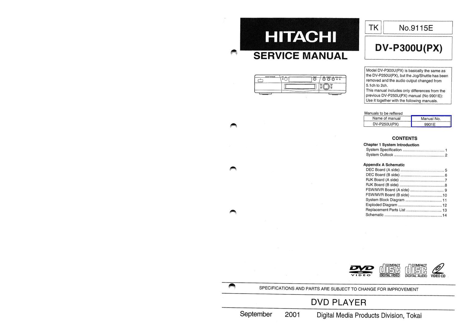
Hitachi DVP 300 U Service Manual

This is the 82 pages manual for Hitachi DVP 300 U Service Manual.
Read or download the pdf for free. If you want to contribute, please mail your pdfs to info@audioservicemanuals.com.

Page: 1 / 82
left right
Hitachi DVP 300 U Service Manual

Extracted text from Hitachi DVP 300 U Service Manual (Ocr-read)


Page 2

PRECAUTIONS FOR SAFETY(PIease follow.)

Before undertaking repair work, please read through this [Precautions for safety].

The following points should be observed in order to prevent accidents from happening and to ensure the
safety of the device.

Cl Degrees of danger or damage that can be caused by faulty operation are indicated by the following marks:

A WARNING

Under this mark, there is "Possible death or serious injury".

A, CAUTION

Under this mark, there is "Possible injury or material damage.

CI The following marks identify actions to be taken:

should pay attention'.

a This mark indicates items to which 'You

0

This mark indicates items 'You have to
accomplish'.

a This mark indicates: 'You should be cau-

tious of electric shock.

®

This mark indicates 'Forbidden items.

& WARNING

D You should pay attention.

Where a special attention is required, it is
indicated by a label or stamp. For example, on
the cabinet, chassis, or parts.

Please respect the indicated items and the
'Precautions for use' of the manual.

El

A

You should be cautious against electric shock.

Please be careful during operations because
there are high voltage and recharging parts
inside. An electric shock or death may happen
by touching them.

When disassembling, assembling, or replacing
a part, the power plug has to be pulled off.
Touching by error a powered part may cause
an electric shock, death, or injury.

III The original part installation and wiring route
shall be restored.

0

For safety, some parts are insulated by a tube
or a tape, or installed without contact with
substrate. The internal wiring ls kept a
distance from hot or high voltage pans by
clamps or routing. Please restore them as
initially done to prevent electric shock or fire
from happening.

'3 Please check safety after servicing.

0

Please check itdismounted screws, pans. and
wires are reinstalled as before and if the area
surrounding the repair is damaged.

Please also measure insulation resistance with
a ohmmeter and to confirm that it is more than
20MQ.

There is risk of electric shock or fire if the
insulation resistance is less than ZOMQ.

D Please use designated parts.

Parts are characterized by uninflammabllity
and voltage resistance, Therefore. parts
having these same characteristics must be
used in replacement.

Especially for parts important in insuring
safety, identified by in the schematic or
parts list, a part with e identical part number
shall be used.

It a part with a different part number is used,
an electric shock or a fire may occur.

r6":

gm,

Chapter _1

System Introduction

System Specification

Specification

General

.......................................... DV-PSOOUtPX)
Sem onductor laser Wave length 650nm(DVD) / 780nm(CD,VCD)
AC110a240V, 50/60 Hz

Model ............
Operating laser
Power supply


Power consumption ........ 3.37::
Weight ..................................................... .
Overall size .............................. 434 (W) x 315 (D) x 98 (H) mm
Allowable operating temperature ........................ +5° C~+35° C
Allowable operating humidity ...................................................... 15-75% (no condensation)
.1 V - 75

Component output terminal Y output level .................... SC 7 Vp_p 2753

PB output level , NT . . p p

..PAL 20.698 Vp-p (75W)
.. NTSC : 0.7 Vp-p (75M

PR output level .

Output terminal

S Wdeo output terminal

.. 1Vp-p (75m
NTSC 0.286Vp-p (75m
.PAL : 0.3Vp-p (75m
.......... S terminal


Y output level ..
C output level ..

Output terminal

Video output

1 Vp~p (synchronous when loaded at 75%
pin jack

Output level .................................
Output trminal .

Audio output

200mVrms (1kHz,<20dB)
.......................................... 1 system (pin jack x 2)

Output level ..
Mixed 20h output.

Sound characteristics : ~ ~
Frequency characteristics ......... CD .4Hz 20kHz (ElAJ)
DVD :4Hz~22kHz (48k sampling)

4Hz~44kHz (96k sampling)

SN ratio
Dynamic range ....................
Total harmonic distortion rate.
Wow/flutter .........................

Measurement llmlt less than (i0.001% W.PEAK)(EIAJ)

Other terminals

.. Coaxial terminal : 1
Optical connector : 1

Digital audio output optical/coaxial .....................
(DTS/AC-S/MPEGZ, LPCM, OFF commutable).

Accessories

Remote control unit
Single 'AAA battery
AV cord .....
Power cord
AC socket ..................................................................................................................

Id-.m.

Chapter 1

Page 66

REPLACEMENT PARTS LIST [FOR DV-P300U(PX)]
SYMBOL SYMBOL

NO P-NO DESCRIPTION NO P-NO DESCRIPTION

2 P_H16683 PANEL TRAY SET 21 5002116 st PWB A83

5 325A966 PANEL FRONT SET 22 5002126 RJK PWB ASS

11 EF13871 CONNECTOR (4PIN) A 23 257A211 POWER UNIT

12 EF13683 CONNECTOR (40PIN) 460A641 OPERATE GUIDE
13 KK10323 RUBBER BELT 261A381 CORD (SPIN)

16 QA12363 TOP COVER 237A482 REMOTE CONTROL
17 335A067 PANEL REAL SET A 261A641 CORD AC

18 U020351 ROM DRIVER

19 5002931 DEG PWB A38

20 5002136 MVR PWB ASS

Appendix A