Hitachi DE 5 Service Manual

This is the 16 pages manual for Hitachi DE 5 Service Manual.
Read or download the pdf for free. If you want to contribute, please mail your pdfs to info@audioservicemanuals.com.

Page: 1 / 16
left right
Hitachi DE 5 Service Manual

Extracted text from Hitachi DE 5 Service Manual (Ocr-read)


Page 1

@HITACHI

SERVICE MANUAL

2 3456

w D»E§ Xffl

No. 396E

D-E5(U)

7 8 9 I

r NEW
d0
wmw

@® ® O®®® ®

CONTENTS

SPECIFICATIONS .............. BLOCK DIAGRAM ............. 7
FEATURES .................. PRINTED WIRING BOARD ........ 3
DISASSEMBLY ............... CIRCUIT DIAGRAM ............ 9
ADJUSTMENTS ............... EXPLODED VIEW .............. 11
LUBRICATIONS ............... REPLACEMENT PARTS LIST ....... 15

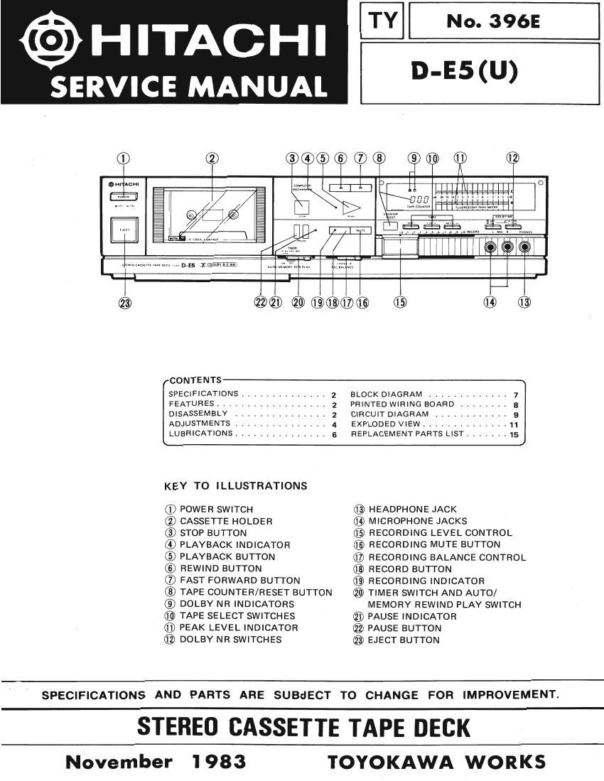
KEY TO ILLUSTRATIONS

(D POWER SWITCH

® CASSETTE HOLDER

® STOP BUTTON

® PLAYBACK INDICATOR
© PLAYBACK BUTTON

© REWIND BUTTON

(D FAST FORWARD BUTTON
TAPE COUNTER/RESET BUTTON
@ DOLBY NR INDICATORS
® TAPE SELECT SWITCHES
® PEAK LEVEL INDICATOR
® DOLBY NR SWITCHES

@ HEADPHONE JACK

MICROPHONE JACKS

® RECORDING LEVEL CONTROL

@ RECORDING MUTE BUTTON

@ RECORDING BALANCE CONTROL

® RECORD BUTTON

RECORDING INDICATOR

® TIMER SWITCH AND AUTO/
MEMORY REWIND PLAY SWITCH

® PAUSE INDICATOR

® PAUSE BUTTON

® EJECT BUTTON

SPECIFICATIONS AND PARTS ARE SUBdECT TO CHANGE FOR

IMPROVEMENT.

STEREO CASSETTE TAPE DECK

November 1983

TOYOKAWA WORKS

Page 2

D-E5

SAFETY PRECAUTIONS

The following precautions should be observed when servicing.

1. Since many parts in the unit have special safety related characteristics, always use genuine Hitachi's replacement parts. Especially
critical parts in the power circuit block should not be replaced with other makers.

Critical parts are marked withAin the circuit diagram.

2. Before returning a repaired unit to the customer, the service technician must thoroughly test the unit to ascertain that it is com-

pletely safe to operate without danger of electrical shock.

SPECIFICATIONS

Track System:
Tape:
Tape Speed:

4 track 2 channel stereo
Cassette tape
4.75 cm/s

Recording System and

Erasing System:
Erase Ratio:

AC bias, 85 kHz
AC erase
65 dB (at 1 kHz) or more

Bias Frequency:

Frequency Response: NOR-I: 20 Hz to 16 kHz
30 HZ to 16 kHZ (:3 dB)

CrOz-Il: 20 Hz to 18 kHz
30 Hz to 16 kHz (:3 dB)

METAL~IVZ 20 Hz to 19 kHZ

Signal to Noise Ratio:

30 Hz to 17 kHz (:3 dBl
Dolby NR OFF: 58 dB (57 dBl
Dolby B NR ON: 66 dB (65 dB")
Dolby C NFl ON: 72 dB (71 dB")
(A weighted, Reference 3% T.H.D.)

Wow and Flutter: 0.04% (WRMS)

0.13%
Distortion: 1% (1 kHz, 160 nWb/m)
Crosstalk: 60 dB (at 1 kHz) or more

t"

"A; VI

A

Input Sensitivity

Microphone: 0.4 mV

(Suntable microphone impedance
300 ohms to 5 kohms)

Line in: 80 mV, 50 kohms

and Impedance:

Output Level

and Impedance: Line out: 500 mV

(Suitable load impedance 50 kohms
or more)
Headphone: 60 mV (8 ohms)
(Suitable load impedance 8 ohms to
2 kohms)

Power Supply: AC 120 V, 60 Hz

Power Consumption: 22 W

Dimensions: 435 (W) x 110 (H) x 218 (D) mm

Weight: 3.7 kg

" According to DIN 45 500

Specifications are subject to change without notice for performance improvement.

FEATURES

1. Built-in Dolby B/C NR circuit 4. Tape stand-by function
2- Auto REC MUTE function 5. Remote control terminal
3. Auto/Memory rewind play function
DISASSEMBLY
1. Top Cover (Fig. 1) 7. Control Buttons (Fig. 6)
Remove two screws ® (1) Playback and stop button
2. Bottom Cover (Fig. 1) After the control P.W,B. and the metal strip are
After top cover is removed, remove screw ® , screw removed, press the {W0 fixing nails ® toward 933")
® (Fig. 7) and screw @(Fig. 8). other as indicated by arrows and remove the play-
3 Cassette Lid (Fig 2) back and stop button.
Press the eject button to open the cassette door. Remove l2l Pause button
nylon rivet, and then pull it upward. After the control P.W.B. and the metal Strip are
4 Front Panel (Fig 3) removed, remove the E-ring to remove the pause
' ' shaft. The , th '
After cassette lid is removed, remove five screws (5), n remove etwo halls.
screw (4) (Fig. 8) and screw© (Fig.8). 8- Mam P-W-B- (Flg- 7)
_ Remove the front panel. Then, remove the screw© and
5' FL meter P'W'B' (F'g' 4 the screw (9 and then remove the P.W.B. setscrew.
After front panel is removed, remove two connectors,
screw ® and screw (D A. 9. Cassette Chassis (Fig. 8)
6 ControlPWB SensorPW B (Fig 5) After the front panel is removed, remove the plastic

Remove the three screws and screw ®, then remove
six nails and plastic rivet.

rivet and two screws 6) , then remove the counter
belt.