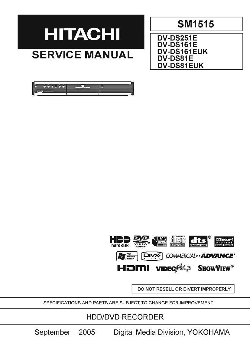
Hitachi D VDS 161 E Service Manual

This is the 63 pages manual for Hitachi D VDS 161 E Service Manual.
Read or download the pdf for free. If you want to contribute, please mail your pdfs to info@audioservicemanuals.com.

Page: 1 / 63
left right
Hitachi D VDS 161 E Service Manual

Extracted text from Hitachi D VDS 161 E Service Manual (Ocr-read)


Page 2

Table of Contents

1 Safety Precaution for Repair ........... 1-1
1-1 Cautions .......................................... ..1-1
1-2 Electrostatic Protection Measures
1-3 Cautions When Handling DVD Drive....,.. -
1-4 Cautions When Handling HDD
1-5 Lead-Free Solder ..........................

1-6 Notes When Using Service Manual ........ 1-5

2 General Description
2-1 Overview .....................
2-1-1 Service method .....
2-1-2 Discinformatiom
2-2 Specifications ........ ..
2-3 Major Differences from Previous Model 2- 5
2-4 Function Differences from

Previous Model ..
2-5 Names of Parts. 2-7
2-6 HDMI Connection .. 2-10
2-7 List of Abbreviations and Terms for DVD

Recorder ..... 2-11

2-6

3 Details of Servicing and

Troubleshooting 3-1
3-1 How to Remove Disc from Faulty
Recorder ................................................ 3-1
3-1-1 Removing Disc without Opening Case. 3-1
3-1-2 Removing Disc from Faulty Recorder M 3-2
3-2 Details of Servicing ................................. 3-2
3-2-1 Setting to defaults at the factory
3-2-2 Troubleshooting HDD ...................
3-2-3 Firmware ............................................. 3-4
(1) Version check procedure ............
(2) Main firmware updating procedure
(3) Loader firmware updating procedure
(4) Main/Loader firmware simultaneous
updating procedure ................................... 3-6
3-3 Troubleshooting ...................................... 3-7
3-3-1 Troubleshooting electronic system 3-7

4 Disassembly and Reassembly ..
4-1 Orderof Disassembly ..
4-2 Disassembly ................
(1) Top Cover ................................................. 4-1

(2 ) Front Panel ............................................... 4-2
(3)T|MER PCB KEY ROB ....4-2
(4) SMPS PCB ...................... ....4-3
(5) JACK PC. B. 4-3
(6) HDD Unit 4-4
(7) CARD RCB ....4-5
(8) MAIN PC. B PCB Frame ................... 4-5
(9) |/O P.C. B Rear Panel FAN Motor ..... 4- 6
(10) DVD Multi Drive ...................................... 4- 7
5 Exploded View and Parts List .......... 5-1
5-1 Exploded View ........................................ 5-1

S Schematic, Wiring Diagrams 6-1
8-1 Wiring Diagram ....................................... 8-1
8-2 SMPS Schematic Diagram ..................... 8-2

8-3 SYSTEM Schematic Diagram(I/O PCB) ...S-3
8-4 TUNER/JACK Schematic Diagram

(l/O P.C.B) .................................................. 8-4
8-5 COMMERCIAL ADVANCE Schematic

Diagram(I/O PCB) ................................. 8-5
8-6 JACK Schematic Diagram ............

S-7 TIMER,KEY Schematic Diagrams
S-B CARD-1 Schematic Diagram

(CARD P.C.B).....
3-9 CARD-2 SchemalIc DIagram

(CARD PCB) ............
S-IO CircuitWaveforms ..... 8-10
8-11 CircuitVoltage Chart ........................... 8-11
C Circuit Board Diagrams C-1
C-1 I/O Circuit Board Diagram ...................... 0-1
0-2 SMPS Circuit Board Diagram C-2
C-3 JACK Circuit Board Diagram 0-2
0-4 LOADER Circuit Board Diagram 0-2
0-5 HDD Circuit Board Diagram... C-2
C-6 TIMER Circuit Board Diagram ,. 0-3
07 KEY Circuit Board Diagram ...... 0-3
0-8 CARD Circuit Board Diagram .. C-3

Contents - 1