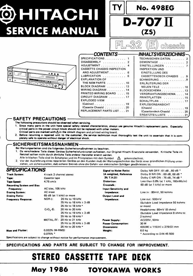
Hitachi D 707 Mk2 Service Manual

This is the 24 pages manual for Hitachi D 707 Mk2 Service Manual.
Read or download the pdf for free. If you want to contribute, please mail your pdfs to info@audioservicemanuals.com.

Page: 1 / 24
left right
Hitachi D 707 Mk2 Service Manual

Extracted text from Hitachi D 707 Mk2 Service Manual (Ocr-read)


Page 1

I§I HITACHI

SERVICE MANUAL

TY

No. 498EG

D-707 H

(ZS)

FLE32 (IE) chassis

CONTENTS-INHALTS VERZEICHNIS?
SPECIFICATIONS ........ 1 TECHNISCHEN DATEN .......
DISASSEMBLY 2 DEMONTAGE ........... 2
ADJUSTMENT ............ 4 EINSTELLUNGEN ......... 7
CASSETTE CHASSIS INSPECTION INSPEKTION UND
AND ADJUSTMENT ........ 6 EINSTELLUNG DES
LUBRICATION ........... 6 CASSETTENDECK-CHASSIS . , 9
EXPLANATION OF SCHMIERUNG ............. 9
THE NEW PARTS ......... IO ERLAUTERUNG DER
BLOCK DIAGRAM ......... 13 NEUEN TELE . . t .10
WIRING DIAGRAM ......... 14 BLOCKSCHEMA ,,,,,,,,,,, 13
PRINTED WIRING BOARD . 15 VERDRAHTUNGSSCHEMA . . . . 14
CIRCUIT DIAGRAM ........ 17 PRINTPLATTEN .......... 15
EXPLODED VIEW SCHALTPLAN ............ 11
(Cabinet) ............... 19 EXPLOSIONSANSICHT
(Cassette Chassis) I ......... 20 (Chassis) ............... 19
REPLACEMENT PARTS LIST . . . 21 (Cassettendeckfihassls) ...... 20
ERSATZTEILLISTE ........ 21
SAFETY PRECAUTIONS fl
Th0 following gar-caution: should b. obs-nod Mun servicing.
'I Since many parts in tho unit hm spacial safety routed characturistics always an yonuina Hitachi s rcplaocm'nt parts. Espocinlly
criticnl parts in the pour circuit block should not b. roplacod with otlm malt-rs
Critical ports art mark-d withAin tho cimuit diagram and printed wiring board.
2. Baler- rnturning a rep-ind unit to tho customr, tin urvico ttcnnician must thoroughly last the unit to curtain that it is com-
pletaly sale to optrato without dunw ol olectrical shock. J
SICHERHEITSMASSNAHMEN a
Eei Wartungurboitcn sind die lolgcnden Sichorhtitsmaanahmcn zu beachtan.
1. Da verschiedene Tails diam Garites Sicherhaitsfunktionon aufwoison, nur Origin»Hitachi-Ersatzteile verwenden. Kritische Teile im
thztcil sollten nicht (lurch éhnliche Teilo endure! Hersteller ersetzt warden.
Alle kritischen Teile sind im Schaltplan and im Printplatten mit dem Symbol A gekennziechnet.
2, Vor der Auslieferung eines repavierten Geriites an den Kunden rnuI3 der Wartungstechniker das Gera't einer grimdlichen Priifung unter-
ziehen, urn sicherzustellen; dell sicherer Betrieb ohne die Gefahr Von elektrischen Schliagen gewfihrleistet ist. J

SPECIFICATIONS Sim-l to Mail. Rntio: Dolby NR OFF: 61 dB , 50 dB "
Track Symm: 4 track 2 channel stereo (A mightld, learonoo Dolby B NR ON : 69 dB, 68 dB "

I Tuna: Cassette tape 3% T.H.DI Dolby C NR 0N : 75 dB, 74 dB '
Tun Spud: 4.75 cm/s Distortion: Less than 08% (at 1 kHz, lSOnWb/m)
According Symm and Bin Crosnulk; 60 dB lat 1 kHz) or more

Froquoncy: AC bias, 105 kHz Input Sontitivity and
Easing Systnm: AC erase Irnpmnca Line in : SOmV, 50 kohms
Erasing Ratio: 65 dB (at 1 kHz) or more Output Ln. nd
Froquoncy Ramona: NOR-I1 20 H1 10 19 '1 lmpodancu: Line out: 500mv
25 Hz to 18 kHz t 3 dB (Suitable Load Impedance 50 kohms
25 Hz to Is kHz' or more)
Grog-II: 20 H2 lo 20 kHz Headphones: 80mV (8 ohms)
25 Hz to 19 RH! t 3 dB (Suitable Load Impedance 8 ohms to
25 Hz to 19 kHz 2 kohms)
METALJV: 20 Hz to 21 kHz Pow supply: AC220V, 50Hz
25 Hz to 20 kHz : 3 (18 Power Consumption: 30 W
25 Hz to 20 kHz Dim-minus: 43st) x 115m) x 279(0) mm
Wall and Fluttor: 0.032% (W-RMS) Woigl'lt: 6.0 kg

0.075% *

Specifications are sublect to change WIthout notice for performance improvsment.

* According to DIN 45 500

SPECIFICATIONS AND PARTS ARE SUBJECT TO CHANGE FOR IMPROVEMENT.

STEREO GASSETTE TAPE DECK

May 1986

TOYOKAWA WORKS