Hitachi D 5500 Service Manual

This is the 62 pages manual for Hitachi D 5500 Service Manual.
Read or download the pdf for free. If you want to contribute, please mail your pdfs to info@audioservicemanuals.com.

Page: 1 / 62
left right
Hitachi D 5500 Service Manual

Extracted text from Hitachi D 5500 Service Manual (Ocr-read)


Page 1

SERVICE MAHIIAI. English No. 1193-1

97%

This unit employs the UD-1 standard mechanism. When Note:

inspecting and repairing this unit, read this together with U USA F3 Switzerland and
th ' I N 1155 fth UD h ' U91 Canada Scandinavia
e serVIce manua ( 0' )0 e mac anIsm( I )' W ...... General Area BS ...... Great Britain
AUI,.... Australia

FSAFETY PRECAUTION

board diagram.

operate without danger of electncal shock.

The following precautions should be Observed when Servicing,

1. Since many parts in the unit have special safety related characteristics,

» always use genuine Hitachi's replacement parts) Especially critical parts
in the power circuit block Should not be replaced with other makers.
Critical parts are marked with A In the schematic diagram, and circuit

2. Before returning a repaired unit to the customer. the service technician
must thoroughly test the unit to ascertain that it is completely safe to

® ®®W®® ® ®

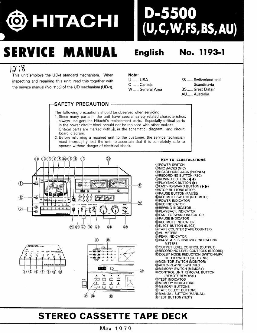
KEY TO ILLUSTALATIONS

(DPOWER SWlTCH

@MIC JACKS (MIC)

@I-IEADPHONE .IACK (PHONES)

@RECORDING BUTTON (REC)

@REWIND BUTION (4 4)

©PLAYBACK BUTTON (p)

@FAST-FORWARD BUTTON (p p)

.STOP BUTTONS (STOP)

©PAUSE BUTTON (PAUSE)

@REC MUTE SWITCH (REC MUTE)

@POWER INDICATOR

@REC INDICATOR

®REWIND INDICATOR

OPLAVBACK INDICATOR

@FAST FORWARD INDICATOR

@PAUSE INDICATOR

@REC MUTE INDICATOR

@EJECT BUTTON (EJECT)

@TAPE COUNTER (TAPE COUNTER)

@vu METERS

@PEAK INDICATOR

@IaIAS/TAPE SENSITIVITV lNDlCATlNG
METERS

@OUTPUT LEVEL CONTROL (OUTPUT)

@RECORDINC LEVEL CONTROLS (RECORD)

@DOLBY NOISE REDUCTION SWlTCH/MPX
FILTER SWlTCH (DOLBY NR)

@MONITOR SWITCH (MONITOR)

@AUTO-REWIND SWITCHES

@MEMORV SWITCH (MEMORY)

@CONTROL UNIT REMOVAL BUTTON
(REMOTE REMOVAL)

@TEST lNDICATOS

@MEMORY INDICATORS

@MEMORV BUTTONS

@TAPE SELECT BUTTONS

@MANUAL BUTTON (MANUAL)

@TEST BUTTON (TEST)

STEREO CASSETTE TAPE DECK

lMau 1 Q70

Page 2

D-5500 I
I

CONTENTS
. SPECIFICATIONS ..................................................... . 4
I BLOCK DIAGRAM (Amplifier and Power supply sections) .......
BLOCK DIAGRAM (Control section) ............................................................
TECHNICALINFORMATION OF ATRS ................................................. .........9
1. Operation and Description of Each Mode ........................................................ 9
2. Initial Start Circuit when the power is switched ON .............................
1) Operation when power is switChed 0N .........
2) Operation immediately after power is switched OFF ............................................. 1o
3. Power OFF, Cassette and Test Mode Stop Detections .............................................. 11
1) Power OFF detection ..................................................................... 11
2) Cassette detection ....................................................................... 11
3) Test mode stop detection ......
4- Tape Selector/Memory Selections ............................................................. 12
1) Tape selector selection .................................................................... 12
2) Memory selection ....................................................................... 13
5. Test Mode Selection ........................................................................ 13
6. Test Data Transfer to Memory ................ I .......... . 14
7. Stop Signal Generation Circuit. . .
8. Battery Alarm Circuit ....................................................................... 15
9. IC HD74145P ............................................................................. 15
10. Memory Indicator Circuit .................................................................... 16

11. Data Storage when power is switched OFF ..........................................
12. Recording/Playback Circuit Block Diagram . . .

13. Playback High Frequency Range Compensation Circuit ............................................. 20
14. Gain Control Circuit ....................................................................... 21
1) Principle of D/A converter (4 bit control signal) ................................................ 21
2) When Z1 -- 24 has pureresistance (R) ........................................ .. 22

3) When 21 - 24 are composed of pure resistance (R) and capacitance (C) . . 22
4) When 21 - 24 are composed of resistance (R) and inductance (L) .................................. 22
5) Low frequency range sensitivity compensation circuit ........................................... 23
6) Medium frequency range compensation circuit ................................................. 23
7) High frequency range compensation circuit .................................................... 23
15. Data Transfer Circuit in Recording Equalizer Section . . . 24
1) Sift resistor (IC511) ..................................................................... 25
2) Multiplex (IC512) ....................................................................... 25
3) Operation of data transfer circuit ........................................................... 25
4) Switching signal generation timing diagram .................................................... 25
16. Bias Oscillator Circuit .................................................. . 27
1) Oscillator circuit ..................... 27
2) Variable recording bias circuit and temperature compensation circuit ................................ 27
3) Bias/E0 test and tape selector detection circuit ................................................ 28
4) Bias setting ............................................................................ 28
17. Test-in-progress Indicator ............ 29
18. Playback Gain Detector Circuit. . . . 29
1) Amplifier and rectifier peak hold circuit ...................................................... 30
2) UR channel switch ...................................................................... 3o
3) Comparison and peak detection circuits ...................................................... 31

_2_