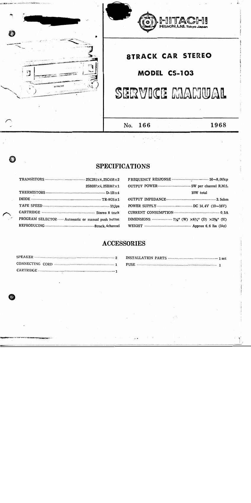
Hitachi CS 103 Service Manual

This is the 16 pages manual for Hitachi CS 103 Service Manual.
Read or download the pdf for free. If you want to contribute, please mail your pdfs to info@audioservicemanuals.com.

Page: 1 / 16
left right
Hitachi CS 103 Service Manual

Extracted text from Hitachi CS 103 Service Manual (Ocr-read)


Page 1

MES'E'AQHE

Hitachl.le. Tokyo Japan

2.x?

8TRACK CAR STEREO

MODEL CS-I O3

§ERW-E MAEJQME.


A
.» No. 1 6 6 l 9 6 8
SPECIFICATIONS
TRANSXSTORS -------------------------- 25C281x4,2$0§58x2 FREQUENCY RESPONSE
253337X4, ZSB357X1 OUTPUT POWER ----------------- 5W per channel EMS.
THERMISTORS ----------- D-IBX4 low total
DIODE - TR»9GSX1 OUTPUT IMPEDANCE 3. Sohm
TAPE SPEED ----------------- 3%ips POWER SUPPLY ---------- ~ DC 14.4V (10~16V)
A CARTRIDGE ................................................ Stereo 3 track CURRENT CONSUMPTION .......................................... 0.5,;
. PROGRAM SELECTOR Automatic or manual push button DIMENSIONS 7%" (W) X6% (D) X395 (3
REPRODUCING ............................................. smkkhanne} WEIGHT ............................... Approx 55 lbs (31;?)
ACCESSORIES
SPEAKER ....................................................................... 2 INSTALLATION PARTS ............................................. 1 set
CONNECTING CORD ........... 1 FUSE ........................................................................ 1
CARTRIDGE ............ 1
Wawvvsmm- M -

my.

Page 2

MQfiEL cstroa SERVICE

DISASSEMBLY

To check, repair and lubricate. disassemble
the player in the following manner.

1. Remove the knobs, escutcheon, and
channel selector button as shown in
Fig. 1.

2. Removal of the top cover

Remove tour screws holding top cover
shown in Fig.2.

3, Removal of the bottom plate

Remove four screws holding bottom

plate.

flow the motor, belt, flywheel, and.
Jlectrical parts (printed circuit board,etc.)

can be inspected.
4. Removal of the printed circuit board

(audio amplifier)

Remove the three screws holding
circuit board shown in Fig. 3. Remove the
volume with the circuit board.

5. Removol of the power amplifier circuit
board and transistor mounting plate

Remove three screws on the output
transistor mounting plate, then remove
two screws holding power amplifier.
Now electrical parts, such as the zenner

(\diode (TR-965), can be checked.

LUBRICATION

Apply oil as shown in Fig.5.

MANUAL

3)
Channel selector button
Escutckeon

washer

. .1.-<»~s.gw«

Top cover
holding screws

Top cover holding
screvs

Bottom plate holding screws

Fig. 2

Output transistor )
mounting plate screws ,

AF amplilier
circuit board
holding screws 1

Power amplifier circuit
board holding screws

Fig. 3 Fig. 4

Gap Between chassis and sliding plate
M

Pitling portion of head
adJustmenl screw and cam

Pan motor oil (l~2 drops)

4 Top and slide surlace ol cam
Grease (apply to all sulaces)

mv-nwnzmrlr.