Hitachi CP 10 EX Service Manual

This is the 8 pages manual for Hitachi CP 10 EX Service Manual.
Read or download the pdf for free. If you want to contribute, please mail your pdfs to info@audioservicemanuals.com.

Page: 1 / 8
left right
Hitachi CP 10 EX Service Manual

Extracted text from Hitachi CP 10 EX Service Manual (Ocr-read)


Page 1

"(I No. I918E

@HITACHI

SERVICE MANUAL CP-IOEX

CONTENTS

Drsassembly
Block diagram
Adjustment

Erase head replacement
Schematic diagram .....

\imewwm

Circuit board diagram...
Exploded view ...................................................... 9
Lubrication .................
Replacement parts list
Inspection of mechanism .................................... 13

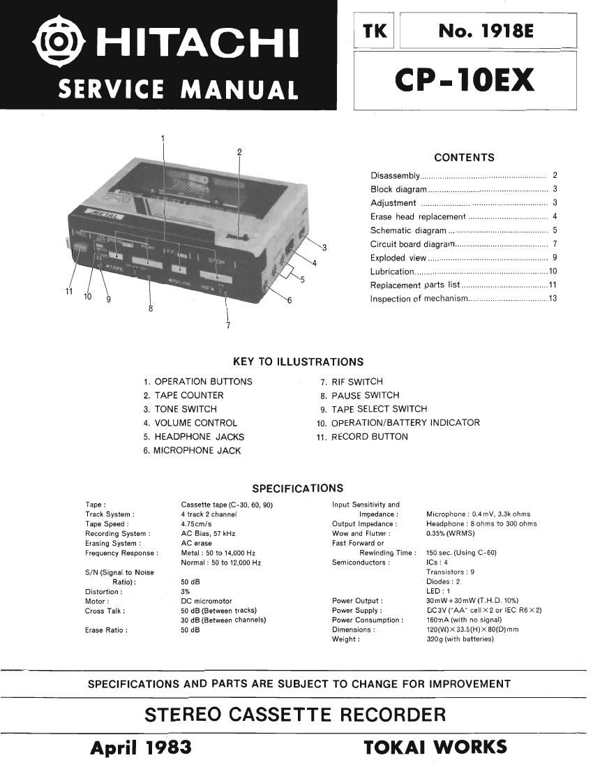
KEY TO ILLUSTRATIONS

. OPERATION BUTTONS
. TAPE COUNTER

. TONE SWITCH

I VOLUME CONTROL

. HEADPHONE JACKS

. MICROPHONE JACK

7. RIF SWITCH

8. PAUSE SWITCH

9. TAPE SELECT SWITCH

10. OPERATION/BATTERY INDICATOR
11. RECORD BUTTON

(Durham--

SPECIFICATIONS
Tape : Cassette tape ((2-30, 60. 90) Input Sensitivity and
Track System : 4 track 2 channel Impedance : Microphone : 0.4mV, 3.3K ohms
Tape Speed : 4.75cm/s Output Impedance: Headphone: 8 ohms to 300 ohms
Recording System : AC Bias. 57 kHz Wow and Flutter : 0.35% (WRMS)
Erasing System : AC erase Fast Forward or

Frequency Response :

S/N (Signal to Noise
Ratio) :

Distortion :

Motor :

Cross Talk :

Erase Ratio :

Metal : 50 to 14,000 Hz
Normal: 50 to 12.000 Hz

50 dB

3%

DC micromotor

50 dB (Between tracks)
30 dB (Between channels)
50 dB

Rewindlng Time:

Semiconductors :

Power Output :
Power Supply :
Power Consumption:
Dimensions 2

Weight :

150 sec. (Using C-GO)

le : 4

Transistors: 9

Diodes: 2

LED : 1
30mW+30mW(T.H.D,10%)

DCBV (AA cell X 2 or IEC R6X2)
160mA(with no signal)
120(W)X3345(H)XBO(D)mm
3209(with batteries)

SPECIFICATIONS AND PARTS ARE SUBJECT TO CHANGE FOR IMPROVEMENT

STEREO CASSETTE RECORDER

April 1983

TOKAI WORKS

Page 2

CP-10EX l

DISASSEMBLY
1. Cassette lid 4. Main PC board
Remove ® (three) screws. Remove © (two) screws.

Tape speed adjustment hole

2. Escutcheon 5. Decoration metal
Remove (five) screws. Remove ® (two) screws.

P1.4)<5

3. Rear case 6. Eject/counter holder
1) Remove © (four) screws. Remove ® (two) screws.
2) Lift the record button side of the chassis a little and
take out the chassis carefully.

® P1.4><2(BLK) . (a