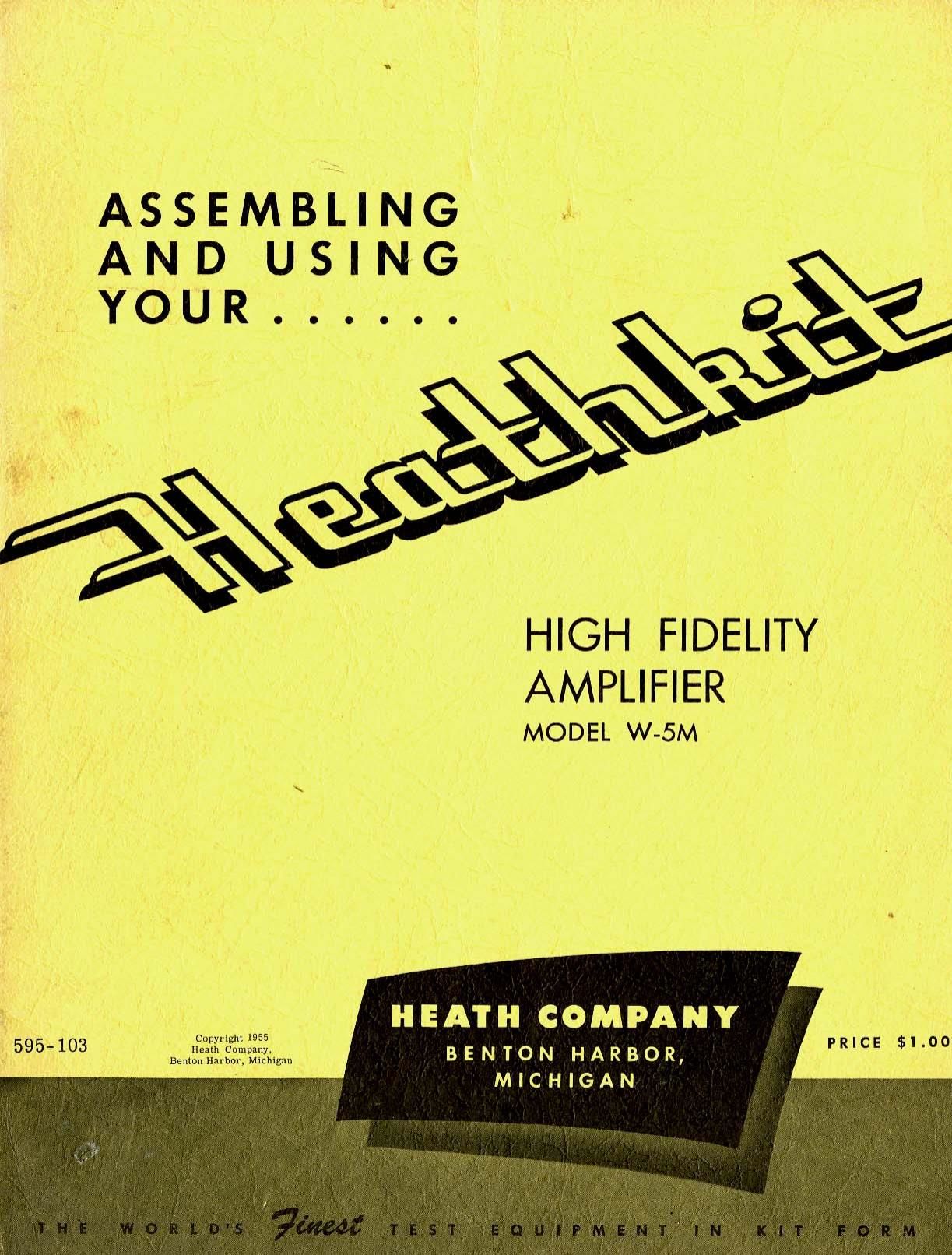
Heathkit W 5M Notice Montage

This is the 36 pages manual for Heathkit W 5M Notice Montage.
Read or download the pdf for free. If you want to contribute, please mail your pdfs to info@audioservicemanuals.com.

Page: 1 / 36
left right
Heathkit W 5M Notice Montage

Extracted text from Heathkit W 5M Notice Montage (Ocr-read)


Page 1

ASSEMBLING
AN D USING
_, YOUR ......


HIGH FIDELITY
AMPLIFIER

MODEL w-5M

HEATH COMPANY
595- 103 Copyright 15155
. BEHIEEIErEZSIZIXIW B E N T O N H A R B O R ,
I MIC H IG A N

PRICE $1.00

Page 2

STANDARD COLOR CODE - RESISTORS AND CAPACITORS

INSULATED FIRST RING SECOND RING THIRD RING
AXIAL LEAD RES|§|0R UNINSULATED BODY comm END COLOR DOT COLOR
Irowu-lnsulolod Color First Figure Second Figure Dlulliplier DISC (ERMIC RM (ODE
llark- Non-insulm-d BLACK 0 0 None 5-Dot t _ 3«Dol
\ EggWN 1 ' 1 0 WW
2 2 00 -
= ORANGE 3 3 ,000 """""°'
YELLOW 4- 4 0.000 EBIII'IIISO
L ToIorIuo GREEN 5 5 00,000
Mulllplior Eiéifil 6 6 0 000,000
In and 2nd Sly-lino! "guns 1 a 7 7 yoooiooo T . C "Ii
m. ....i mi..... i... awE g g 033333-333 '"' "
In digll bond doolalo wldth ' '
now. run nor RESISTOR 5-00! RADIAl lEAD CERAMK cMACITOII mmm RANGE rc cmmc mm
Multiplier Tomp. Cool. (GP-("V

MolleIlor

Tolorlnn

TC Mulflpllor Multlpllor Toloronu

RADIAL LEAD (BAND) RESISTOR
MuIIiIIIIor

21d "er

Mlltlpllor

Tololnnlo Isl Figur-

IY-PASS COUPLING CERAMIC CAPACITOR
(opium


AXIAL lEAD CERAMIC CAPACITOR

Iomp. (MIT. (upotity

Toloronto

Tolovonto

The standard color code provides all necessary information re-
quired to properly identify color coded resistors and capacitors.
Refer to the color code for numerical values and the zeroes or
multipliers assigned to the colors used. A fourth color band on
resistors determines tolerance rating as follows: Gold = 5%.
silver = 10%. Absence of the fourth band indicates a 20%
tolerance rating.

The physical size of carbon resistors is determined by their
wattage rating. Carbon resistors most commonly used in Heath-
kits are V2 watt. Higher wattage rated resistors when specified
are progressively larger in physical size. Small wire wound
resistors 1A watt. 1 or 2 watt may be color coded lut the first
band will be double width.

MOLDED MICA TYPE CAPACITORS


CURRENT STANDARD (ODE RMA 3-DOT (OISOLETE) IUTTON SILVER MICA
WhitollMA) Itsgsignifironl Tlguvo {:3 In an. 500 W.V.D.C. i 20% TOL (SSAPACITOR c
""I 0 Mumpliu nu . """i'u" mum. 3:1
CODE i I I
7 (loss Til-rum! 235ilflmflfl' "I". Mympmrsrd Ilia" "d In"
I % RMA (5-DOT OISOLETE CODE) RMA 6-DOT (OBSOLETE) EMA vDOT (OBSOLETE)
5' - Worhin m I
2 d Slgnlfixonl hum I mi ® loloronu
n m-hipli" Voltage -- \\\\ \ll w- Mulflplior 23:: sIfllifiIllE Nauru \ Working Voltlpo
Front RS R\ x

Isl 2nd Sig-Ilium! Flynn

at 8% ® Mulflplilr

a :13 x xxxo ...... .
_ . i . , I Sinnlfironthnuu
Toloronn Worllng \\ \\\\ ® ToIIromo Working Voltag-
Vultogo lonlr

MOLDED PAPER TYPE CAPACITORS


. r um. (on: APACITOR
TUIUlAR CAPACITOR In} Mm, "m mowilzmfldflmclmk I c ... sums..."
MIINFIi" Working Volts Si v" midi linen
Normally "I
= = stump-d for lady
voluo
Tolorunce 2nd swfifi. Multiplier WINNIE"
I; Voltngo "qu 1nd
ti::2':.::'::°:;i".'r.terrier*""- x=«i°'"'"" ......m...

The tolerance rating of capacitors is determined by the color
code. For example: red = 2%, green 2 5%, etc. The voltage
rating of capacitors is obtained by multiplying the color value
by 100. For example: orange = 3 X 100 or 300 volts. Blue
6 X 100 or 600 volts.

In the design of Heathkits. the temperature coefficient iif ceramic
or mica capacitors is not generally a critical factor and there-
fore Heathkit manuals avoid reference to temperature coeffi-

cient specifications.
(Gunny oi Commlob

Page 27

( ) Snap the top cover in place by lining the cover studs up with the appropriate holes in the
chassis and pressing down gently on all four corners until firmly settled.

This completes the assembly and adjustment of your Heathkit Amplifier model W-5M. See Page
27 for Installation and Operation.

IN CASE OF DIFFICULTY
Recheck the wiring. Trace each lead in colored pencil on the pictorial as it is checked in the
amplifier. Most cases of difficulty result from wrong connections. Often having a friend check
the wiring will reveal a mistake consistently overlooked.

If possible, compare the tube socket voltages with those shown in the voltage table below. Read-
ings within 20% of those shown may be considered as normal. If a discrepancy is noted, check
the associated circuits carefully. Any component in those circuits should be suspected until
proven satisfactory.

If voltages and tubes are normal, try the following procedure.

With the preamplifier output disconnected from the amplifier input, touch tube socket terminal
V4-5 with one lead of a .01 Mid condenser, holding the other lead in your hand. (CAUTION: Do
not touch the chassis or any other metallic body with your other hand while making this test.
Dangerously high voltage is present throughout the circuit and due care should be exercised.)
This should cause a hum level to be evident in the speaker, if the circuit from this point is nor-
mal. Work on forward in the circuit, touching terminals V3-5, VZ-G, V2-7, V2-1, V2-2, Vl-8,
V1-6, V1-7, Vl-l and V1-2. The hum level should increase somewhat as you work back toward
the amplifier input. At some point in the amplifier, the circuit will appear to be dead and all
circuitry following that stage may be disregarded in your trouble shooting. In this way, you can
easily locate the source of the trouble and expedite its correction.

VOLTAGE CHART

SOCKET
TUBE TYPE

V1
1 2AU7
V2
1 2AU7
V3
KT66
V4
KT66
V5
5R4GY
AA
POWER
G
CONDENSER
H
CONDENSER

Pin 1 Pin 2 Pin 3 Pin 4 Pin 5 Pin 6 Pin 7 Pin 8 Pin 9

88 NS 2.2 Fil. 280 88 100 Fil.

255 NS 13 Fil. 255 NS 13 Fil.

TP 47 Fil. 480 480 *8.3 TP 485 Fil. 50

TP 12.5 Fil. 475 480 *6.7 TP 480 Fil. 50

NC ** 510 TP 495 455 VAC TP310 455 VAC TP 240 ** 510

Fil. Fil. 0 400 300 110 VAC Switch Circuit

A 380 l 400 . 350

A 235 . 245

All voltages positive DC to chassis, measured with Heathkit V-7 VTVM with 11 megohm input
resistance. Voltages taken with Heathkit WA-P2 Preamplifier connected.

TP - Tie point. NS - Not significant. Line voltage - 117 volts AC.

Fil. - Voltage between points so designated, 6.3 volts AC.

* Voltages so designated will vary with changes of settings of Bass-Ba] control.

** Voltages between pins 8 and 2 - 5 volts AC.

Page 25