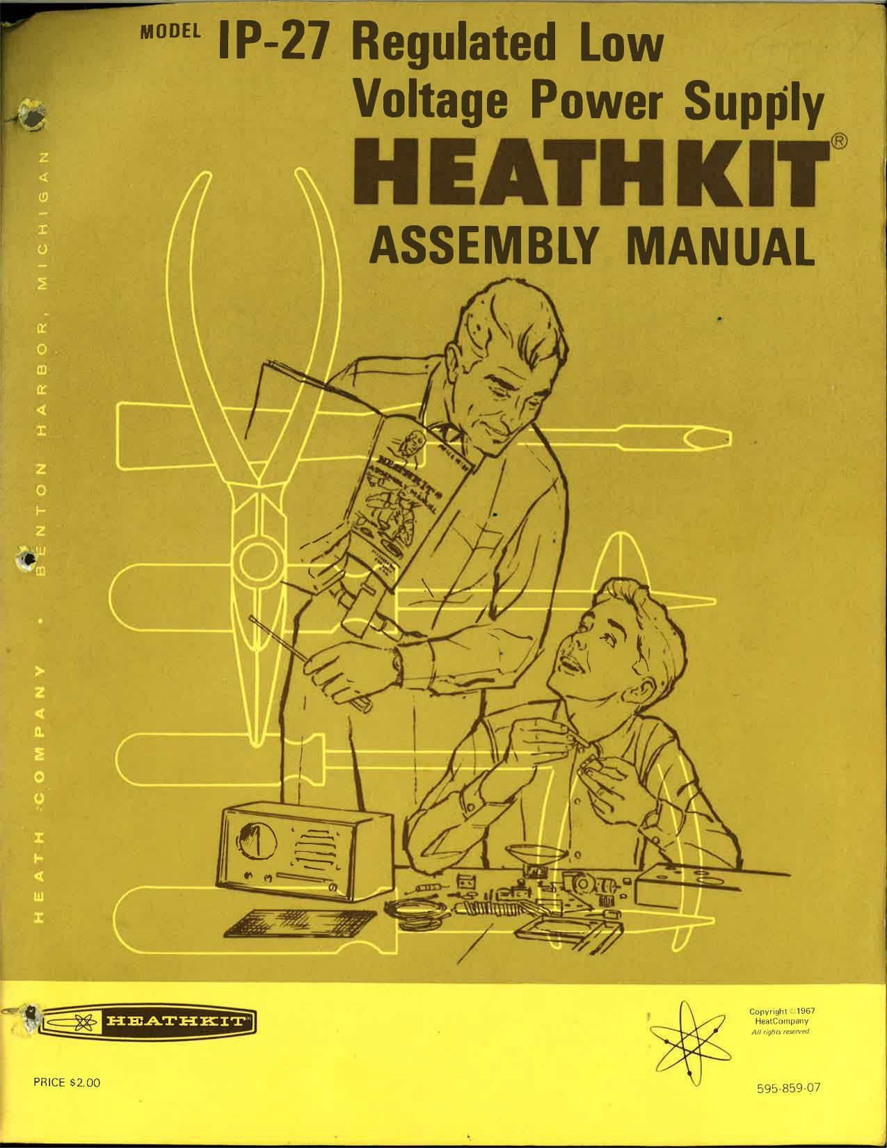
Heathkit IP 27 Manual

This is the 74 pages manual for Heathkit IP 27 Manual.
Read or download the pdf for free. If you want to contribute, please mail your pdfs to info@audioservicemanuals.com.

Page: 1 / 74
left right
Heathkit IP 27 Manual

Extracted text from Heathkit IP 27 Manual (Ocr-read)


Page 1

W 'IP:2i7_. Réguliated Low
Voltage Power Supply
HEATH KI'I'®

gar? ASSEMBLY MANUAL 3

Copyrigm ' 1967
HeatCumpany
All [W (mm;

PRICE $2.00

I+W|

Page 2

.%

e

Dear Custo mer:

The Heathkit electronic product you have purchased is one of the best performing electronic products in the
world.

Here's how we aim to keep it that way:
-- Ynur HeathkitWarranty

During your first so days of ownership, any parts whlch we find are defective, either in materials or
workmanshlp, will be replaced or repaired free of charge. And we'll pay shipping charges to get those parts to
you - anywhere in the world. -

lf we determine a defective part has caused your Heathkit electronic product to need other repair, through no
fault of yours, we will service it free - at the factory, at any retail Heathkit Electronic Center, or through any of
our authorized overseas distributors.

This protection is exclusively yours as the origlnal purchaser. 'Naturallv, It doesn't cover damage by use of
acidcore solder, incorrect assembly, misuse, fire, flood or acts of God. But, it does insure the performance of
your Heathkit electronic product anywhere in the world - for most any other reason.

After-Warranty Service

What happens after warranty? We wont let you down. If your Heathklt electronic product needs repairs or you
need a part, just write or call the factory, your nearest retell Heathkit Electronlc Center, or any Heath
'- authorized overseas distributor. We maintaln an inventory of replacement parts for each Heathkit model at most

locatlons - even for many models that no longer appear in our current product line-up. Repair service and

technical consultation are available through all locations. .

We hope you'll never need our repair or replacement services, but it's nice to know youre protected anyway »
and that cheerful help is nearby.

Sincerely,

HEATH COMPANY;
Benton Harbor, Michigan49022

% WWWW .

74 WW WWWWWWWWTW a


c

Page 21

Page 14

( D/Cut a 1-1/8" length of sleeving and slide it
over one lead of the other 27 KS! (red-violet-
or nge) resistor.

( ~ Connect the sleeved lead of this 27 K9. resis-
tor to lug 9 on switch AG (S-l).Connect the
other lead to lug 2 onterminal strip AN (NS).

( Wpare a 7-5/8" length of blue wire and a
7-5/8" length of yellow wire, andtwist them

together as shown in Pictorial 5.

( /)/At one end of this twisted pair, connect the
yellow wire to lug 8 (S-2) and the blue wire
to lug 6 (S-2) on the front water of switch
AK. Position the twisted pair as shown.

(Wthe other end of this twistedpair, connect
the yellow wire to lug 2 (8-2) and the
blue wire to lug 1 (5-2) of terminal strip
AN.

wrepare a 2" length of yellow wire. Then
connect one end of this wire to lug 2 of

control AJ (5-1). The other end will be con-
nected later.

This completes the assembly and wiring of the
front panel section. Set the front panel aside until
it is called for later. -

REAR PANEL ASSEMBLY
Refer to Pictorial 6 for the following steps.

NOTE: When hardware is called for in a step, only the screw
size may be given. For instance, if 632 x 3/8 hardware is
called for, it means that a 6-32 x 3/8 screw, one or more #6
lockwashcrs, and a 6-32 nut should be used. (Do not use the
black 6-32 x 3/8 screws until they are specifically called
for.) The Detail referred to in the step will show the proper
number of lockwashers to use.

CAUTION: When you install the heat sink plate in the next
step, be sure to position it with its sharp hole edges against
the rear panel. (A sharp edge facing out could cut through a
mica insulator and short out a transistor.) The holes in the
heat sink plate should line up with the holes in the rear panel.

-HEATHKIT


0-6v32 NUT

r-u LOCKWASHER
.lii

Taé LOCKWASHER

v-l-LUG TERMINAL
STRIP

TOP or its

REAR PANEL

SHARP HOLE EDGES
ON THIS SIDE

MATCH UP HOLES
BEFORE TIGHTENING
SCREWS

HEAT SINK PLATE

.-642xa/B"
scszw

Detail 6A

L/

( ) Refer to Detail 6A and install the heat sink
plate on the lettered side of the rear panel
with 6-32 x 3/8" hardware. Installthe 1-lug
terminal strip with two #6 lockwashers at
BA.

( Cut a small slit in the side of the silicone
grease container as shown in Detail 6B.

NOTE: Before you install the transistor in each
of the next few steps, first spread a coating of
silicone grease on the flat surface of the tran-
sistor. Then place the mica insulator on this
greased surface and spread more silicone
grease on the other side of the insulator. The
grease will help conduct heat from the transis-
tor to the chassis.

PUSH
HERE

[V

CUT SMALL
SLIT

Detail 65

4

3

Page 48

HEATHKIT

Page 31

If the resistance readings you obtain in the
initial tests are not within i20% of the values
given in the steps, refer to the In Case Of
Difficulty section of this Manual. After the dif-
ficulty has been located and repaired, return
to this part of the Manual and complete the
Resistance Tests.

NOTE: A Power Supply front panel meter indi-
cation will be given in each of the next few steps.
This meter indication is for VTVM and volt-
ohm-milliammeter readings only. If a Heathkit
Model IM-25 Solid-State VOM is being used, the
Power Supply meter will only show a slight up-
ward deflection for each of these measurements
because the Ohms test voltage is very low.

IMPORTANT: Since you will be measuring re-
sistance in semiconductor circuits, you must be
sure of the polarity of your ohmmeter test leads.
To do this, perform the next four steps.

1. Turn your ohmmeter range switch to its
highest resistance range; then connect its
test leads to the terminals on the meter in
the Power Supply.

2. Change the ohmmeter range switch to sue-
cessively lower ranges until the Power Sup-
ply meter begins to deflect in either direc-
tion.

3. If the Power Supply meter deflects up-scale,
the lead that is connected to the + meter
terminal is the positive ohmmeter lead, and
the other is the negative ohmmeter lead.
If the meter deflects to the left, the ohm-
meter leads are reversed.

4. Disconnect the ohmmeter leads from the
Power Supply meter.

Place the ohmmeter on the RX1000 scale.

Connect the negative ohmmeter lead to the
negative (-) Power Supply binding post, and
C connect the positive ohmmeter lead to the
positive (+) Power Supply binding post. The
ohmmeter should indicate 4700 (l and the
Power Supply meter should deflect upwards
to about one-fourth of full scale.

at)

( ) Turn the COARSEVVOLTAGE switch to the

Ofx .5-5 V position. The resistance should re-
main around 4700 S2 and the Power Supply
meter should deflect about the same as in
the previous step.

Turn the COARSE VOLTAGE switch to the
5-10 V range. Resistance should increase to
15 K9 and the Power Supply meter reading
should decrease.

()
QR

Turn the COARSE VOLTAGE switch to the
10-15 V position. The resistance indication
and the Power Supply meter reading should
remain about the same.

( )
0)

Turn the COARSE VOLTAGE switch to the
15-20 V position. The resistance shouldin-
crease to 47 K9, andthe Power Supply meter
deflection should decrease.

( )

or.

( ) Slowly turn the COARSE VOLTAGE switch

through each of the remaining positions. The
resistance should remain at 4'7 KS2 and the
Power Supply meter reading should remain
about the samE.

0K

( 'V) Return the COARSE VOLTAGE switch to the
AC OFF position.

Place the RESET-STANDBY switch in the
DC ON position. The ohmmeter reading
should decrease to around 500 n, then
slowly increase to over 1100 Q as 500 pfd
capacitor 09 charges.

(.)

Connect the negative ohmmeter lead to the
chassis and touch the positive ohmmeter
lead alternately to one of the mounting
screws on each of the transistors on the
Power Supply rear panel. Readings from all
screws to the chassis should show infinite
resistance.

W) 0ch

Page 62

LIMITER

AMMETEI

BIAS SUPPLV

FULL WAVE
RECTIFIER
Am FILTER

REFEREKE
VOLTAGE

SUPPLY

m
' AMMETER DC
I wanna mums REGULATION 4
LIMITER com-am. VT
02.
anon
DETECTOR
°3- RELAY
A MPLI PIER
an, as ssms
REGUL non
VOLTAGE
cournou.

BLOCK DIAGRAM

Page 68

Page 49

H E AT H K I '1
PART PRICE DESCRIPTION PART PRICE DESCRIPTION
N 0. Each N0. Each

lNSULATORS-GROMMETS

75-60 .10 Mica insulator

75-88 .10 Transistor insulator case
481-3 .10 Capacitor mounting wafer
73-45 .10 1/2" grommet

75-71 .10 Line cord strain relief

WIRE HARNESS-WIRE-SLEEVING

134-151 3.15 Yire harness
344-2 .05/ft arge black wire
344-3 .05/ft Large red wire
344-31 .05/ft Large brown wire
344-50 .05/ft Small black wire
344-52 .05/ ft Small red wire
344- 54 .0 5/ ft Small yellow wire
344-56 .05/ ft Small blue wire
340-2 .05/ ft Bare wire

346- 1 .05/ ft Sleeving
HARDWARE

#2 Hardware

250-175 .05 2-56 x 3/8" screw
254-7 .05 #3 lockwasher
252-51 .05 2-56 nut .

#6 Hardware

250-229 .05 6-32 x 1/4" phillips head
screw

250-303 .20 6-32 x 1/4" decorative screw

250-270 .05 6-32 x 3/8" black screw

250-89 .05 6-32 x 3/8" screw

250-26 .05 6-32 x 5/8" screw

250-304 .15 6-32 x 3/8" stud

250-227 .05 6-32 x 7/8 phillips head
screw

250-365 .05 #6 x 1/4" sheet metal screw

254-1 .05 #6 lockwasher

259-1 .05 #6 solder lug

253-1 .05 #6 flat fiber washer

253-2 .05 #6 shoulder fiber washer

255-13 .05 #6 x 1/4" spacer

255-15 .05 #6 x 1/2" spacer

255-1 .05 Insulator case spacer (thick)

255-74 .10 Insulator case spacer (thin)

252-3 .05 6-32 nut

#8 Hardware

250-437 .05
254-2 .05
252-4 .05

Other Hardware

253-10 .05
254-4 .05
259-10 .05
252-7 .05
252-32 .05

METAL PARTS

8-32 x 3/8" screw
#8 lockwasher
8-32 nut

Control washer
Control lockwasher
Control solder lug
Control nut
Push-on Speednut

Chassls-Cabinet Parts

203-476 1.20
203-477 1.35
200-484 1.15
204-767 .40
204-759-1 .10
90-350-2 3.40
210-35 3.75

Other Metal Parts

205-545 .20
204-565 .10
207-2 .20
260-24 .30

MISCELLANEOUS

Front panel

Rear panel
Chassis

Siderail

End cap

Cabinet half shell
Bezel

Heat sink plate

Relay mounting bracket
Capacitor mounting clamp
Diode clip

Electrical Components

54-180 10.60
69- 71 3.40
407-120 8.60
412-15 .1 5
413-10 .10
413-14 .30
421-25 .30
89-23 .80
432-27 .40

Power transformer
Relay

Meter

Neon lamp

Red lens

Amber lens

1-1/2 ampere slow-blow
fuse

Line cord

Line cord adapter