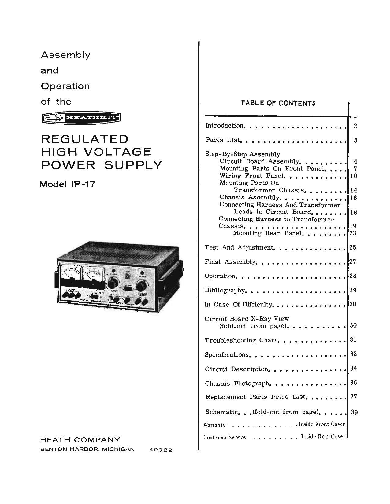
Heathkit IP 17 Manual

This is the 44 pages manual for Heathkit IP 17 Manual.
Read or download the pdf for free. If you want to contribute, please mail your pdfs to info@audioservicemanuals.com.

Page: 1 / 44
left right
Heathkit IP 17 Manual

Extracted text from Heathkit IP 17 Manual (Ocr-read)


Page 1

Assembly
and
Operation

of the
HEAII-IKIT

REGULATED

HIGH VOLTAGE
POWER SUPPLY

Model lP-17

HEATH COMPANY
BENTON HARBOR. MICHIGAN

49022

TABLE OF CONTENTS

Introduction..................
Parts List...................

Step-By-Step Assembly
Circuit Board Assembly. . . . . . .
Mounting Parts On Front Panel. .
Wiring Front Panel. . . . . . . . . .
Mounting Parts On

Transformer Chassis. . . . . .
Chassis Assembly. . . . . . . . . .

Connecting Harness And Transformer
Leads to Circuit Board. . . . . . .

Connecting Harness to Transformer

.

ChassiS.....................

Mounting Rear Panel. . . . . .
Test And Adjustment. . . ........-
FinalAssembly................
Operation. ...................
Bibliography..................
InCase0fDifficulty.............

Circuit Board X-Ray View

(fold-out from page). . . . . . . . . .

Troubleshooting Chart. . . . . . . . . . . . .

Specifications. . . . .............
Circuit Description. . . . . . . . . . . . .
Chassis Photograph. . . . . . . . . . . . .

Replacement Parts Price List. . . . . .

Schematic. . .(101d-out from page). . . . . .

Warranty ............. Inside Front Cover

Customer Service ......... Inside Rear Cover

10

14
16

18

19
23

25
27
28
29
30

30
31
32
34
36
37

39

Page 2

Page 2

-C% HEATHKIT'

INTRODUCTION

The Heathkit Model IP-l'? Regulated HV (High
Voltage) Power Supply is a compact, convenient
source of variable regulated high voltage, vari-
able bias voltage, and filament voltage for lab-
oratories and workshops. Separate panel meters
are provided for accurate monitoring of the DC
output current and voltage. All output binding
posts are insulated from the chassis to allow the
high (3+) and bias (C-) voltages to be used as
either negative or positive voltage sources.

Separate transformers are used for filament
and high voltage supplies so the filament circuit
may be left on while switching off the high voltage
circuit. This eliminates repeated tube warmup
time. The dual windings on the transformers can
be wired to operate from either 105-125 or
210-250 volts AC.

A meter switch permits you to monitor either
the high voltage or the bias voltage on the front
panel voltmeter. The special taper C- VOLTS
control provides a finer adjustment of low values
of bias voltage. Built-in circuit protection pre-
vents damage i.f the bias voltage output circuit
should accidentally be short circuited or over-
loaded, and the input circuit of the Regulated
High Voltage Power Supply is fused for additional
protection against overload conditions or short
circuits. You will find that all of these features,
plus the attractive compact styling, will make
this Power Supply a useful and valuable asset on
your workbench.

Refer to the "Kit Builders Guide" for complete
information on unpacking, parts identification,
tools, wiring, soldering, and step-by-step as-
sembly procedures.

Page 43

DC ON-STANDBY SWITCH

In the DC ON position, this switch appliespower
to the high voltage transform er in the Power Sup-
ply. DC voltage will be present at the appropriate
output binding posts. No DC voltage will be pres-
ent when the switch is in the STANDBYposition.

B+ VOLTS INDICATOR

Indicator lamp will glow when AC POWER switch
is ON and the VOLTMETER switch is in the 34:-
position.

\\/

M/
New
®

/

\\\"

l /

B+ VOLTS CONTROL

Controls the 13+ voltage available at the B+
VOLTS output binding posts.

VOLTME TE R SWITCH

Switches the Voltmeter to read either the output
voltage available at the C~ output binding posts
or the voltage at the B+ output binding posts.
C- voltage is indicated on the Oto 150 volt scale
and B+ volts is indicated on the 0 to 400 volt
scale.

B r VOLTS OUTPUT

Provides from 0 to 400 volts of regulated DC at
currents up to 100 ma.

CHASSIS GROUND

Allows either common (COM) Power Supply out-
put to be connected to chassis ground.

C- VOLTS OUTPUT

DC up to 1 ma.

Provides negative voltage from 0 to -100 volts

AC POWER SWITCH

Turns the AC power on and off. With this switch
in the ON position, power is applied to the fila-
ment transformer and to the DC ON-STANDBY
switch. Filament voltage is thus applied to the
tubes in the Power Supply and to the 6.3 and
12.6 volt filam ent output binding posts.