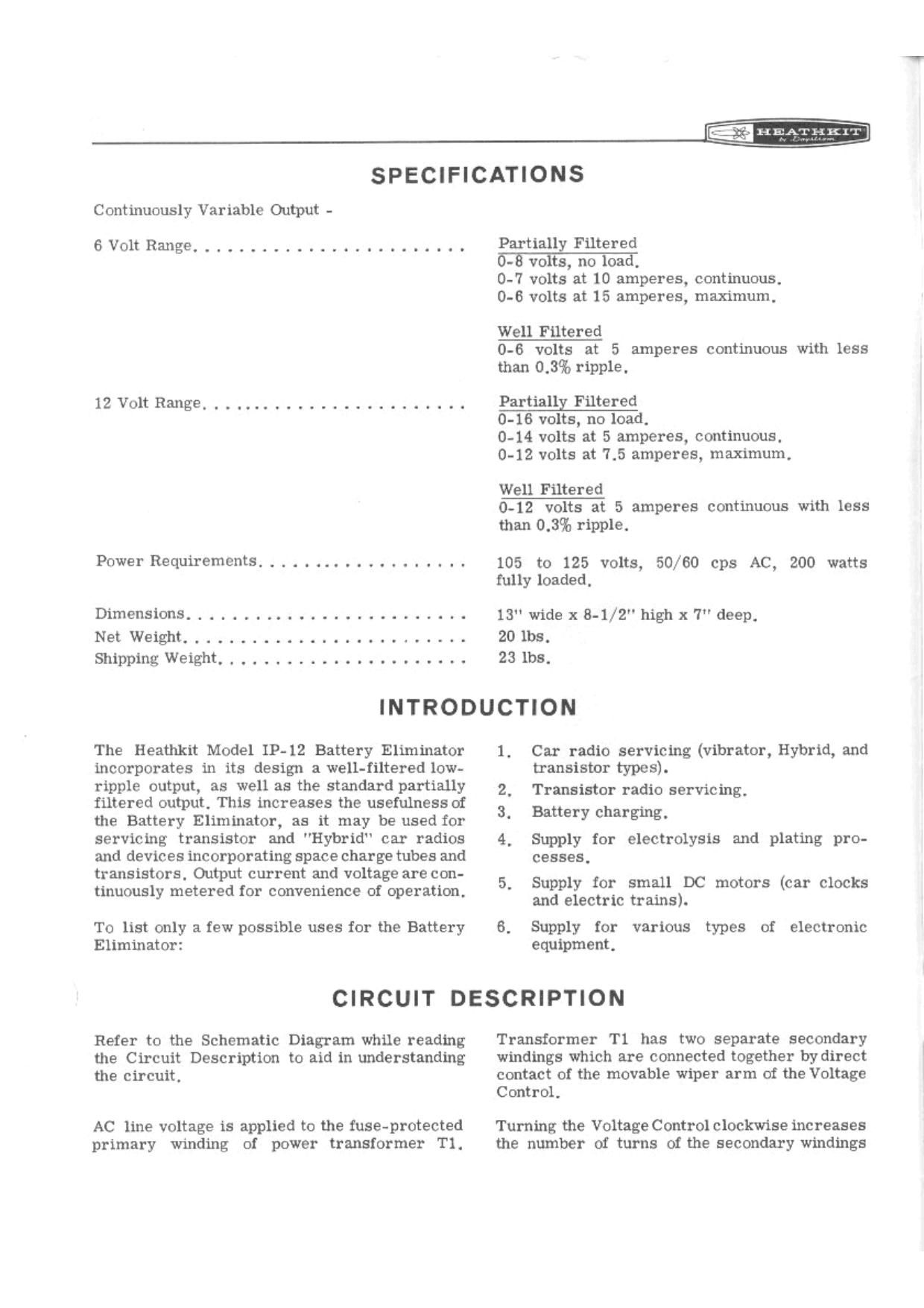
Heathkit IP 12 Schematic

This is the 2 pages manual for Heathkit IP 12 Schematic.
Read or download the pdf for free. If you want to contribute, please mail your pdfs to info@audioservicemanuals.com.

Page: 1 / 2
left right
Heathkit IP 12 Schematic

Extracted text from Heathkit IP 12 Schematic (Ocr-read)


Page 1

.34.. 171 EA'iiiiiiFJ

SPECIFICATIONS

Continuously Variable Output -
6VoltRange. ............
12VoltRange....... .............

.o.......-......

Power Requirements. . .

Partially Filtered
5-5 volts, no load,
0-7 volts at 10 amperes, continuous,
0-6 volts at 15 amperes, maximum.

Well Filtered
0-6 volts at 5 amperes continuous with less
than 0.3% ripple.

Partially Filtered
0-16 volts, no load.

0-14 volts at 5 amperes, continuous.
0-12 volts at 7.5 amperes, maximum,

Well Filtered
0-12 volts at 5 amperes continuous with less
than 0.3% ripple.

105 to 125 volts, 50/60 cps AC, 200 watts
fully loaded,

Dimensions. . . . . . . .. . . . - . . .......... 13 wide x8-l/2" highx7"deep.

NetWeight.. ..... Zles.

ShippingWeight...................... 23ibs.
INTRODUCTION

The Heathkit Model 113-12 Battery Eliminator
incorporates in its design a well-filtered low-
ripple output, as well as the standard partially
filtered output. This increases the usefulnessof
the Battery Eliminator, as it may be used for
servicing transistor and "Hybrid car radios
and devices incorporating space charge tubes and
transistors, Output current and voltage are con-
tinuously metered for convenience of operation.

To list only a few possible uses for the Battery
Eliminator:

1. Car radio servicing (vibrator, Hybrid, and
transistor types).

2, Transistor radio servicing.
3. Battery charging,

4, Supply for electrolysis and plating pro-
cesses,

5. Supply for small DC motors (car clocks
and electric trains).

6. Supply for various types of electronic
equipment,

CIRCUIT DESCRIPTION

Refer to the Schematic Diagram while reading
the Circuit Description to aid in understanding
the circuit.

AC line voltage is applied to the fuse-protected
primary winding of power transformer T1.

Transformer Tl has two separate secondary
windings which are connected together bydirect
contact of the movable wiper arm of the Voltage
Control.

Turning the Voltage Controlclockwise increases
the number of turns of the secondary windings

Page 2

that are used. thus applying more voltage to the
rectifier circuit, This voltage can be varied
from 0 to approximately 8 volts, depending on
the load connected to the output terminals of the
Battery Eliminator.

6 VOLT OPERATION

With the Range Switch in the 6 Volts position,
the power rectifier, magnesium copper sulfide
diodes 01 through D4, is connected to form a
hill-wave bridge rectifier. See Figure 1. The
ripple in the resulting DC voltage from the recti-
fier- is then partially filtered (smoothed) by (:3.-
pacitor C1, From C1, the DC voltage is applied
through the ammotcr to the partially filtered
positive (1) output terminal.

Figure 1

Additional filtering is provided by choke LI
and capacitor C3, which reduce the ripple,
This DC voltage is available between the

\ ."\
wit-gal) we #03) WI

negative {-) and the Well Filtered positive (r)
output terminals , The voltmeter is connected be-
tween the Well Filtered output terminals.

12 VOLT OPERATION
Placing the Range Switch in the 12 Volts posi-
tion connects the power rectifier diodes as a

voltage-doubler circuit toproduce [ht-f necessary
higher voltage. See Figure 2 The ripple in the

0+ 0+ 1463+

Figure 2

+@ +@

resulting: DC voltage is partially filtered by ca-
pacitors Cl and C2. and is applied through the
nmmctor to the Partially- Filtered output tur-
minals, Additional filtering is provided by choke
AC] and capacitor (33 and is available at. the
Well Filtered terminals.

PARTICALLY mTERED

n +® 0+

+
: 10,000 uFD
' 10 Volt:

so . so Cycles

SWITCH SHOWN m/
5 vou po smON

we {'N W5 m4 wa

99;

+
= 10,000 uFD
_ 10 Volt:

SCHEMATIC OF THE
I-IEA'I'IMI' BATTERY ELIMINATER
MODEL 11 - 12