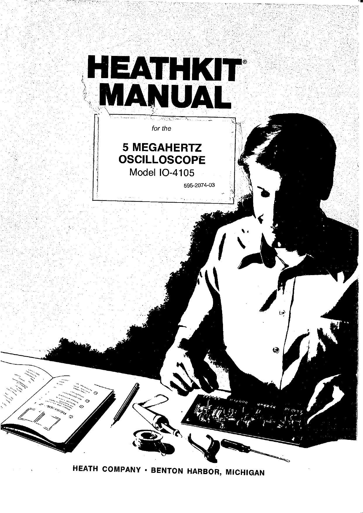
Heathkit IO 4105 Manual

This is the 112 pages manual for Heathkit IO 4105 Manual.
Read or download the pdf for free. If you want to contribute, please mail your pdfs to info@audioservicemanuals.com.

Page: 1 / 112
left right
Heathkit IO 4105 Manual

Extracted text from Heathkit IO 4105 Manual (Ocr-read)


Page 1

for the

5 MEGAHERTZ
OSCILLOSCOPE
Model IO-4105

595-2074-03

HEATH COMPANY - BENTON HARBOR, MICHIGAN

Page 2

HEATH COMPANY PHONE DIRECTORY
The following telephone numbers. are direct lines to the departments listed:
Kit orders and delivery information . . . . . . .. (616) 982-3411

Credit ...... ....... (616) 982-3561
Replacement Parts i , i . . . .. ....... . .................... (616) 982-3571

Technical Assistance Phone Numbers
8:00 AM. to 12 RM. and 1:00 RM. to 4:30 P.M., EST, Weekdays Only

Ft/C. Audio, and Electronic Organs . ............. (616) 982-3310
AmateurRadio... ........ ....(616)982-8296
Test Equipment, Weather Instruments and

Home Clocks ................. ......... ......... ...(616) 982-3315
Television....;............ ....... ............ (malaria-3307,
Aircraft, Marine, Security, Scanners, Automotive,

Appliances and General Products . .. . - . . . . . . . . (616) 982-5496
Computers ..... .M,..........,...(618)9826309


YOUR HEATHKlT 90-DAY LIMITED WARRANTY

Consumer Protection Plan for Heathkit Consumer Products

Welcome to the Heath iamily. We believe you will enloy assembling your kit and will be pleased with its
pertormance. Please read this Consumer Prolectlon Plan careiully, It Is a "LIMITED WARRANTY ea
detihed in the us. Consumer Product Warranty and Federal Trade Commission Improvement Act. This
warranty gives you speciiic legal rights, and you may also have other rights which vary irom state to state.

Heaths Responsibility

PARTS - Replacements tor iactcry detective pans will be supplied lies ior so days irom date oi purchase. Replacement pans are
warranted lor the remaining portion oi the original warranty period. You can obtain warranty parts direct irom Heath Company by writing
or telephoning us at (516) 982-3571. And we will pay shipping charges to get those pans to you . . . anywhere in the world.
SERVICE LAEoR - Fora period ol so days lrom thedate oi purchase. any matiunctton caused bydeiective pans or error In design will
be corrected at no charge to you. you musl deliver the unit at your expense to the Heath tactory. any Heathkit Electronic Center (units oi
Ventechnoiogy Electronics Corporation). or any at our authorized oversees distributors,

TECHNICAL CONSULTATION » You will receive tree consultation on any problem you might encounter in the assembly or use oi your
Heathklt product. Just drop us a line or give us a call. Sony. we cannot accept collect calls.

NOT COVERED ~ The correction or assembly errors. adjustments. calibration. and damage due to misuse. abuse. or negligence are
not covered by the warranty. Use oi conoslve solder and/or the unauthorized modiiicatton ol the product or at any turnished component
will void this warranty in its entirety. This warranty does not include reimbursement ior rnconveniehce. loss oi use. customer assembly.
set~up time. or unauthorized service.

This warranty covers only Heath products and Is not extended to other eoulpment or components that a customer uses In conjunction with
our products.

SUCH REPAIR AND REPLACEMENT SHALL BE THE SOLE REMEDY or THE CUSTOMER AND THERE SHALL BE NO LIABILiTy
ON THE FAFIT 0F HEATH FOR ANv SPECIAL. INDIFIECT. INCIDENTAL on CONSEQUENTIAL DAMAGES. INCLUDING BUT NOT
LlMITED TO ANY Loss or BUSINESS OR PROFITS. WH ETHEFI on NOT FoRSEEAELE. -

Some states do not allow the exclusion or limitation ot incidental or consequenllal damages, so the above limitation or exclusion may not
apply to you.


Owners Responsibility
EFFECTIVE WARRANTY DATE - Warranty begins on the date oi Ihst consumer purchase. you must supply a copy oi yourprooi oi
purchase when you request warranty service or pans. to
ASSEMBLV- Before seeking warranty service, you should complete the assembly hy carelully lollowing the manual Instructions.
Heathkit service agencies cannot complete assembly and adjustments that are customers responsibility.
ACCESSORY EQUIPMENY v Perlormarica maltunctlons involving other nonrHaath accessory equipment, (antennas. audio compo-
nents. computer peripherals and soitware. etc.) are not covered by this warranty and are the owners responsibility.
SHIPPlNG UNITS - Follow the packing lnstmcllonspublished in ltie assembly manuals. Damagadue to inadequate packing cannot be
repaired under warranty.

It you are nul satlsiled with our service (warranty or otherwise) or our products. wills dlractly to our Director at

Customer Ssh/ice. Healh Company. Benton Harbor MI 45022. He will make certain your problems reoalve
Immedlale. personal altantlon.

Heathkit® Manual

for the

5 MEGAHERTZ
OSCILLOSCOPE
Model IO-4105

595-2074-03

WARNING

Do not expose this
oscilloscope
to rain or moisture.

HEATH COMPANY
BENTON HARBOR, MICHIGAN 49022

Copyright © 1979

Heath Company

All Rights Reserved

Printed in the Unlted States of America

Page 27

Page 24

Cfii-IEATHKITO

HORIZONTAL _

CIRCUIT BOARD

Open the pack marked #2 and check each part against

Page 25

PARTS LIST

the following list. The key numbers correspond to the
numbers on the Horizontal Circuit Board Parts Picto-

rial (Illustration Booklet, Page 3].

To order a replacement part, always include the
PART NUMBER. Use the Parts Order Form furnished
with the kit. If one is not available, see Replacement
Parts inside the rear cover. For prices, refer to the

separate Heath Parts Price List.

KEY HEATH QTY. DESCRIPTION

No. Part No.

RESISTORS

All resistors are 5% (fourth band gold) unless designated 10%

(fourth band silver).

NOTE: The resistors may be packed in more than one en-
velope (stamped RES). Open all the resistor envelopes in this
pack before you check the resistors against the Parts List.

1/2-Watt

A1 6-279 1 2.7 n (red-viol-gld)

A1 6-100 5 10 0 (brn-blk-blk) 1/
."

A1 6-1 Ijo 2 47 0 (yeI-vlol-blk) :7

A1 6-1 .11 2 100 o (brn-blk-brn)

A1 6-221 8 220 .0 (red-red-brn) \/

A1 6-271 2 270 9. (red-viol-brn) /

A1 6-631 2 330 n (org-org-brn) 1/

A1 6-891 1 390 Q (org-wht-brn) /

A1 6-511 2 5100 (grn-brn-brn) /

A1 6-561 2 560 0 (grn-blu-brn) 1/

A1 6-821 1 820 n (gry-red-brn) 1/

CIRCUIT KEY HEATH QTY. DESCRIPTION CIRCUIT
Comp. No. No. Part No. Comp. No.
Resistors (Contd.)
A1 6-102 / 13 '1000 o (brn-blk-red) R12, R202,
R204, R218,
R219, R221,
R227, R245,
R262, R266,
R273, R276,
R262
A1 6-152 1 /1500 0 (brn-gm-red) R248
1/ R277 A1 6-162 5 / 1600 n (brn-gry-red) R205, R206,
R213, R216,
R250
R244. R269, A1 6-222 1/ 2200 0 (red-red-red) R272
R270. R275, A1 6-682 1 6600 o (blu-gry-red) R226
R276 A1 6-103 1 1/ 10 k0 (brn-blk-org) R256
R214, R215 A1 6-153 1 f 15 k0 (brn-grn-org) R210
R241, H281 A1 6-475 2' 47 k0 (yel-viol-org) F1220, F1222
R230, R237, A1 6-663 11/ 66 kn (blu-gry-org) R225
R236, R246, A1 6-104 5 / 100 k0 (brn-bIk-yel) R201, R239,
R253, R254, R246, R252,
R259, R260 / R274
R212, R255 A1 6-664 1 660 km (blu-gry-yel) R224
R209: 223 A1 6-314 1 910 k0 (wht-brn-yel) R242
R229 A1 6-105 1 / 1 M0 (brn-bIk-grn) R260
206 R207 A1 1-163 1/ 6.6 MD. (blu-gry-grn) R223
2:133 258 A1 1-166 1,, 10 M0 (brn-blk-blu) R240

-HEATI-IKITE
KEY HEATH QTY. DESCRIPTION CIRCUIT KEY HEATH QTY. DESCRIPTION CIRCUIT
No. Part No. Comp. No. No. Part No. Comp. No.
Other Resistors DIODES
A2 6-681-1 IA 680 n, 1-watt, 5% R232 D1 56-56 3 /1N4149 D201, D204,
/ (blu-gry-brn) D207, D208,
A3 1-23-2 2 5600 o, 2-watt R286, R265 D209, D210,
/ (grn-blu-red) , ' D213, D214
A4 5-2-2 2 22 k0, 2-watt R233, R264 D1 56-59 / 1 1N750A D206
' D1 56-67 ,/ 2 VR10A D205, D211
CAPACITORS
Ceramic TRANSISTORS - INTEGRATED CIRCUITS
(ICs)
B1 . 21-157 11/5pF 0219
B1 21-7 1 1/ 38 pF 0204 NOTE: Transistors and integrated circuits are marked
B1 21-32 2 /47 pF 0220, C235 for identification in one of the following four ways:
B1 21-121 2 --/56 pF 0205, 0213
B1 21-75 11/ 100 pF c212 1, part number.
:1 21721 1 1/200 P: 0222 2. Type number. [On integrated circuits this
81 21:: a 27:: F 2:: 0218 refers only to the numbers and letters listed.
' C229, Any additional letters or numbers on an IC
B1 21-16 2 / .01 0F +1 0202, c224 are Hm Slgnificant']
B1 2182 1 / 02 MF 0210 3. Part number and type number.
B1 21499 a / '1 0F 0209, 0228 4. Part number with a type number other than
0232 the one listed.
Tantalum-Electrolytic E1 417-134 5 /MP86520 transistor 0209, 0210,
914 / uec Wyfic 0212' Qm'
01 25-224. 1 2.2 ,7me 0203 '/ 0217
02 25-620 2 ./ 10 F NP (non-polarized) C203, 0221 '52 417454 1 2N2359 translslor 0216
electrolyfic E1 417-235 2 \/2N4121 transistor 0203, 0204
C2 25415, g ,/10 0F eIemrolyfic 0206, 0217) E1 417-801 4 /MPSA20 transistor 0202, 0205,
C223, C225, / 0206, 0211
0226 0227 E3 417-834 2 MPSU10 translstor 0214, 0215
0230' 0231 E4 417-902 3/ 5566 transistor 0201, 0207,
0234 J 0205
02 25-233 1 /22 ,1F electrolytic 0207 E5 443-6 1 7474 "3 U201
E5 445-22 1 74121 IC U205
E5 443-23 1 / 74122 lC U203
E5 443-44 1 J7413 IC U204
Other Capacitors E5 443-625 1 1/ 74132 IC U202
03 29-5 11/ 1000 pF polystyrene 0216
C4 27-47 1 .1 RF Mylar 0201
C5 27-2 1 /1 MP film C215

Page 59

Page 56

_I-IE.A.THKIT@

Refer to Pictorial 4-4 [Illustration Booklet, Page 12) for
the following steps. ,

Connect the leads from transformer T1 to switch
SW10 as follows. Make mechanically secure connec-
tions. (See the inset drawing on Pictorial 4-4.)

(f) Black~green lead to lug 5 (5-1).

( 4 Black lead to lug 6 (NS).

( 4 Black-yellow lead to lug 2 (8-1).

( (r Black-red lead to lug 3 (NS).

Connect the wires coming from BO#7 in the harness
as follows. Make mechanically secure connections.

( /) Either large brown wire to fuse block F1 lug 2
(8-1).

( /)/ Other large brown wire to switch SW10 lug 3
(3-2).

( /) Connect a 1 bare wire [remove all the insula-
tion from a 1" length of brown wire) from
capacitor CS lug 4 (8-1) to solder lug N (NS).

Connect the wires coming from BO#9 in the harness
as follows:

( if Allfiveblack wires to solder lugN (8-6). Be sure
all wires, especially the lower ones, get sol-
dered.

( f Both violet wires to capacitor C3 lug 1 (NS).
.1 . . .

( "{ Both white-red w1res to capacrtor C3 lug 2 (NS).

( M) Red wire to capacitor C3 lug 3 (NS).

( Jr Place a 1" length of sleeving on each lead of a
500 .0, 10-watt resistor.

( If R14: Connect this resistor to capacitor C3 be-
tween lugs 1 (S-3) and 2 (NS). Position this
resistor directly above the capacitor lugs.

( /) Place a 5/8 length of sleeving on each lead of a
270 .0, 3-watt resistor.

0 1/ 1/2 3/4 1 (mouse) 2 3
I1IBIGBI"{.7{BI.I 1.1 |. . .
ImuIImI . I I I r I . I . I . I I I
o '6 1 (cm 2 a 4 5 s 7 a

(/) R15: Connect this resistor to capacitor C3 be-
tween lugs 2 [8-4) and 3 (8-2). Position this
resistor 1/2 above the chassis.

Refer to Pictorial 4-5 (Illustration Booklet, Page 12) for
the following steps.

( 4' Locate the power supply circuit board and posi-
tion it as shown. '

Connect the wires coming from BO#3 of the harness
to the power supply circuit board as follows:

[ /] White-green wire to hole S (3-1).
[/) White wire to hole R (S-l).

( 4/) Green wire to hole AA (8-1).
V)" Violet wire to hole AD (3-1).

(4 White-gray to hole Y (S-l).

Connect the wires coming from BO#4 of the harness
to the power supply circuit board as follows:

[/) Either gray wire to hole Q (S-l).
( v) Other gray wire to hole V (S-l).
( ,)' Any of the three yellow wires to hole N (S-l).

( xf Either of the remaining yellow wires to hole T
(3-1).

( J" Remaining yellow wire to hole AH (S-l).

Connect the wires coming from BO#5 of the harness
to the power supply circuit board as follows:

(4 Black wire to hole D [S-l).

( V) Either orange wire to hole P (S-l].
( ) Other orange wire to hole U (8-1).
( f White-red wire to hole I (S-l).

( j/ White-yellow wire to hole L (8-1).

[ ) White-brown wire to hole K (S-l].

I-IE.AIII-IIEIJZ'IIe

&

Page 57

POWER SUPPLY
CIRCUIT BOARD

0\
6-32 X 3/16"
SCREW

L-l egg
3

PICTORIAL 4-6

Connect the wires coming from BO#6 of the harness
to the power supply circuit board as follows:

( 1 Large black wire to hole AE (8-1).
(4' Large orange wire to hole X (8-1].
( /) Large red wire to hole W (8-1).

[ 1) Large yellow wire to hole AF (S-1).

Refer to Pictorial 4-6 for the following steps.

Connect the leads coming from the transformer T1 to
the power supply circuit board as follows:

( r Large white-yellow lead to hole AB (3-1).
(/) Either large yellow lead to hole E (S-l).

( /) Other large yellow lead to hole C (84).

[ I') Large white-brown lead to hole I (S-l).

( /) Large white lead to hole H (S-l).

'( /) Either large red lead to hole F (3-1).

( w) Other large red lead to hole G (8-1).

A

(

( A Other large brown lead to hole B (8-1).

Either large brown lead to hole A (8-1).

This completes the wiring to the power supply circuit
board. Be sure all connections are soldered, and cut
off all excess lead lengths as close to the foil as possi-
ble.

( 4 Temporarily mount the power supply circuit '
board at hex studs CH and CL with 6-32 X 3/15"
screws.