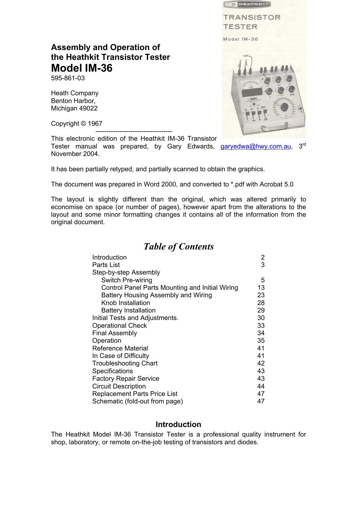
Heathkit IM 36 Manual

This is the 63 pages manual for Heathkit IM 36 Manual.
Read or download the pdf for free. If you want to contribute, please mail your pdfs to info@audioservicemanuals.com.

Page: 1 / 63
left right
Heathkit IM 36 Manual

Extracted text from Heathkit IM 36 Manual (Ocr-read)


Page 1

TRANSISTOR
TESTER

Model lM-36
Assembly and Operation of
the Heathkit Transistor Tester

Model IM-36

595-861-03

Heath Company
Benton Harbor,
Michigan 49022

Copyright © 1967

This electronic edition of the Heathkit lM-36 Transistor
Tester manual was prepared, by Gary Edwards, gamedwa@hwy.com.au, 3rd
November 2004.

It has been partially retyped, and partially scanned to obtain the graphics.

The document was prepared in Word 2000, and converted to *.pdf with Acrobat 5.0
The layout is slightly different than the original, which was altered primarily to
economise on space (or number of pages), however apart from the alterations to the

layout and some minor formatting changes it contains all of the information from the
original document.

Table of Contents

Introduction 2
Parts List 3
Step-by-step Assembly

Switch Pre-wiring 5

Control Panel Parts Mounting and Initial Wiring 13

Battery Housing Assembly and Wiring 23

Knob Installation 28

Battery Installation 29
Initial Tests and Adjustments. 30
Operational Check 33
Final Assembly 34
Operation 35
Reference Material 41
In Case of Difficulty 41
Troubleshooting Chart 42
Specifications 43
Factory Repair Service 43
Circuit Description 44
Replacement Parts Price List 47
Schematic (fold-out from page) 47

Introduction

The Heathkit Model lM-36 Transistor Tester is a professional quality instrument for
shop, laboratory, or remote on-the-job testing of transistors and diodes.

Page 2

Direct readings of DC Beta (gain) from O to 400 and accurate measurements of
currents and leakage in transistors permit testing under simulated operating conditions.
These conditions are set up by switch-selecting the voltages and currents that are
applied to the transistor elements to duplicate published characteristics.

Four lever switches permit eight different tests and measurements, which result in a
comparative quality figure (beta, gain) rather than the simple good-bad test made by
many other transistor testers.

The self-contained power supply, that consists of seven readily obtainable standard D-
cell batteries, makes the instrument fully portable. Since no battery current is drawn
unless a transistor is being tested, long battery life is assured.

External voltage sources for higher values of bias, collector, or leak voltages, can be
connected to convenient binding posts for higher voltage transistor testing.

Diodes can be tested for fonNard and reverse characteristics under appropriate current
conditions.

By following the step-by-step assembly, test, and operating instructions in the manual,
you can build, test, and use this instrument in a few hours.

The attractively styled cabinet, functionally designed control panel, and efficient
circuitry, combine to give you a transistor tester that you will use with confidence for
many years.

Refer to the "Kit Builders Guide" for complete information on unpacking, parts
identification, tools, wiring, soldering, and step-by-step assembly procedures.

Parts List

Note: the numbers in parenthesis in the Parts List are keyed to the numbers on the
Parts Pictorial (Fold-out from Page 5).

To order replacement parts, refer to the "Replacement parts Price List" on Page 47 and
use the Parts Order Form furnished with this kit.

Note: Precision resistors may be marked in 0, KO, or MO. (KQ equals 10000, MQ
equals 1,000,0000).

Parts Per
Part No. Kit Description
Resistors
Precision 1%, 0.5 watt.
(1) 2-148 1 0.090
2148 1 0.90
2-229 1 20
(2) 2-19 1 90
2-230 2 180

224 1 900

Page 31

In a like manner, install the other
battery spacer bracket and cable clam
at BB.

Install 6-32 speednuts at each of the
holes on the battery housing flange as
shown in Pictorial 13. Be sure that the
flat side of each speednut faces
upward.

Position the battery housing as shown in
Pictorial 14 for the following steps.

()

Locate the battery pack wire harness
and pass the four wires of breakout #3
through both cable clamps as shown
in the pictorial.

Prepare the following lengths of bare
wire. To prepare the bare wire, first
cut the indicated lengths of red wire.
Then remove all the insulation from
each length.

3 X 1-%", and 2 X 2-%"

Connect these bare wires to the solder lugs
on the battery pack as follows:

()
()

2-%" from lug 2 (NS) to lug 3 (S-1).
1-%" from lug 4 (S-1)to lug 5 (NS).
1-%" from lug 8 (S-1)to lug 9 (NS).
1-%" from lug 10 (NS) to lug 11 (8-1).

2-%" from lug 12 (S-1)to lug 13 (NS).

Connect the wires from breakout #3 of the
battery pack harness to the lugs on the
battery housing as follows:

()

Yellow to lug 1 (8-1).
Red to lug 2 (8-2).
Brown to lug 9 (8-2).

Orange to lug 10 (3-2).

1 Hum 92
ammufi fl unaunAr
we mm. .

unar- mouwu
ms.

M Luz-1r
. ltlrw

Dela" 13E

5-32lI/4' SCI!"

OUYSIDE 0F
BAYVEIV uousmc

l6 LOCIWA NE!

6')! "Milan:
sucu

Detail 13C

6»)! NUV

lo Lac-(runs:

)/I' (AM!
(LAMP

. ' KW
° nun s: mun/4" scum

Detail 130

Connect the wires from breakout #2 of the bottom pack harness to the lugs on the
battery housing as follows:

()

Black to lug 5 (3-2).

Page 35

( ) Press a knob firmly onto only the BIAS control bushing with the pointer at the 7
o'clock position.

() With the bushing installed on it, remove the BIAS knob. Then press the knob
bushing firmly into the knob with the handle of a screwdriver.

scunomvn
no

m. um l
IUHGINC OFENIKO

mm: V
nun
ovum:
Inco-
nun-mo
[MOI
pomru Imo-

Detall 17A

Page 49

EBl - E32
1131 - 132

DC Collector Resistance

DC collector resistance is defined as collector voltage Ec divided by collector current Ic;

that is, Rc : E.
10

To find DC collector resistance, set up a given bias condition, press the Collector
Current lever and adjust the Bias control. Read collector current Ic. Raise the
Collector Voltage lever and read collector voltage Ec.

AC collector resistance

AC collector resistance is defined as a change in collector voltage (Ec) divided by the
change in collector current (lc) with the base current (l3) held constant; that is,
A EC

Alc

IB constant.

To find AC collector resistance, set up a low collector voltage condition. Press the
Collector Current lever and adjust the Bias control. Read collector current lc2. Now
raise the Collector Voltage lever to read collector voltage E02.

Increase the Collector Voltage switch setting, use the same bias setting as above,
and read Ecl. Now push the collector current lever and read Ic1.

Ecl - E02
lo] -102

Using the values just found, calculate AC collector resistance as follows:
Transistor Leakage Tests

logo = collector to base leakage with the emitter open.

Adjust the Leak Voltage switch to the specified voltage, and set the Leak Current
switch to the proper meter range. Press the ICBO lever and read leakage current
directly.

ICEO = collector to emitter leakage with the base open.

Adjust the Leak Voltage switch to the specified voltage, and set the Leak Current
switch to the proper meter range. Raise the logo lever and read leakage current
directly.

ICES = collector to emitter leakage with base shorted to the emitter.

Connect a shorting wire between the Base and Emitter binding posts. Then read ICES
on the meter, using the same procedure as outlined above for Icfio.

ICER = collector to emitter leakage with a specified resistance connected between the
base and emitter.