Heathkit IM 2260 Manual

This is the 12 pages manual for Heathkit IM 2260 Manual.
Read or download the pdf for free. If you want to contribute, please mail your pdfs to info@audioservicemanuals.com.

Page: 1 / 12
left right
Heathkit IM 2260 Manual

Extracted text from Heathkit IM 2260 Manual (Ocr-read)


Page 1

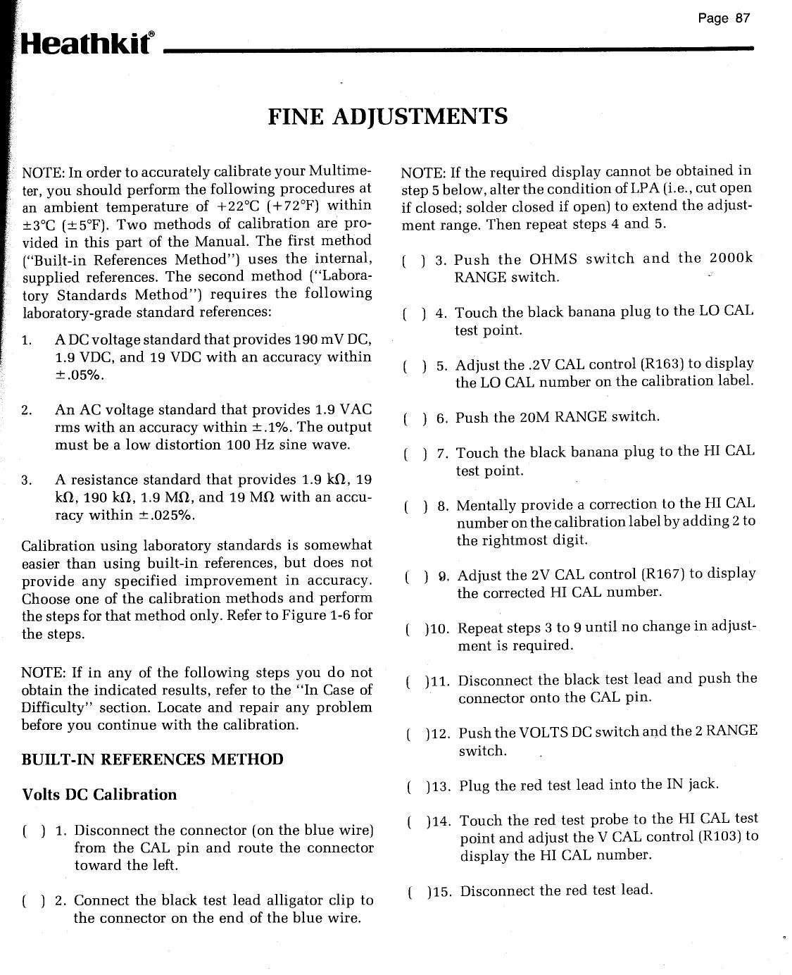
Page 87

iHeathkita

NOTE: In order to accurately calibrate your Multime-
i- ter, you should perform the following procedures at
an ambient temperature of +22°C (+72°F) within
t3°C (:5°F]. Two methods of calibration are pro-
vided in this part of the Manual. The first method
(Built-in References Method) uses the internal,
supplied references. The second method (Labora-
tory Standards Method) requires the following
laboratory-grade standard references:

1. A DC voltage standard that provides 190 mV DC,
1.9 VDC, and 19 VDC with an accuracy within
1.05%.

2. An AC voltage standard that provides 1.9 VAC
rms with an accuracy within : .1%. The output
must be a low distortion 100 Hz sine wave.

3. A resistance standard that provides 1.9 k0, 19
kt), 190 k0, 1.9 MI), and 19 M0 with an accu-
racy within 1.025%.

Calibration using laboratory standards is somewhat
easier than using built-in references, but does not
provide any specified improvement in accuracy.
Choose one of the calibration methods and perform
the steps for that method only. Refer to Figure 1-6 for
the steps.

NOTE: If in any of the following steps you do not
obtain the indicated results, refer to the In Case of
Difficulty section. Locate and repair any problem
before you continue with the calibration.

BUILT-IN REFERENCES METHOD

Volts DC Calibration

[ ) 1. Disconnect the connector (on the blue wire)
from the CAL pin and route the connector

toward the left.

( ) 2. Connect the black test lead alligator clip to
the connector on the end of the blue wire.

FINE ADJUSTMENTS

NOTE: If the required display cannot be obtained in
step 5 below, alter the condition of LPA (i.e., cut open
if closed; solder closed if open) to extend the adjust-
ment range. Then repeat steps 4 and 5.

l ] 3. Push the OHMS switch and the 2000k
RANGE switch. '

( ] 4. Touch the black banana plug to the LO CAL
test point.

t ) 5. Adjust the .2V CAL control [R163] to display
the LO CAL number on the calibration label.

( ) 6. Push the 20M RANGE switch.

( ) 7. Touch the black banana plug to the HI CAL
test point.

[ ) B. Mentally provide a correction to the HI CAL
number on the calibration label by adding 2 to
the rightmost digit.

( ] 9. Adjust the 2V CAL Control (R157) to display
the corrected HI CAL number.

[ )10. Repeat steps 3 to 9 until no change in adjust-
ment is required.

( ]11. Disconnect the black test lead and push the
connector onto the CAL pin.

[ )12. Push the VOLTS DC switch and the 2 RANGE
switch.

( ]13. Plug the red test lead into the IN jack.

l )14. Touch the red test probe to the HI CAL test
point and adjust the V CAL control (R103) to
display the HI CAL number.

( ]15. Disconnect the red test lead.

Page 2

Heathkitfi

Volts AC Calibration

NOTE: If necessary, refer to AC CAL Circuit Assem-
bly on Page 66 and assemble the AC CAL circuit.
Then proceed with the following steps.

()1.

()3

()4.

()5.

Insert the 1/4 loop ends of the AC CAL circuit
into the IN and COM jacks of the Multimeter
with the diode side of the circuit positioned at
the IN jack.

. Push the red test lead plug into the lug hole

on the diode side of the AC CAL circuit.

Push, the black test lead plug into the remain-
ing lug hole of the AC CAL circuit.

Connect the black test lead alligator clip to a
known earth ground.

Push the VOLTS DC switch and the 200
RANGE switch.

WARNING: When the test probe tip is connected to an
AC outlet, hazardous voltages will be present at sev-
eral places. These are shown by the boxed-in areas in
Figure 1-5. Also avoid excessive movement of the AC
CAL circuit so you do not short out the line voltage.

()5-

()8.

With caution, touch the test probe tip to the
line voltage source and observe the display. If
no voltage is obtained on one side of the AC
outlet, try the other side. Note the voltage
display and remove the test probe tip from the
line voltage source.

. Refer to Figure 2-1 (Illustration Booklet, Page

19) and determine the equivalent AC line vol-
tage that corresponds to the voltage you ob-
served in step 6 above.

Remove the AC CAL circuit from the Mul-
timeter and connect the test leads directly to
the IN and COM jacks.

. Push the VOLTS AC switch and the 200

RANGE switch (for 120 VAC line voltage) or
the 750 RANGE switch (for 240 VAC line
voltage).

( 112.

. Be sure the black test lead alligator clip is still

connected to a known earth ground.

. Carefully touch the test probe tip to the line

voltage source and adjust the AC CAL control
(R123) for the equivalent AC voltage display
determined from Figure 2-1. There may be
some variation in the display. Make the ad-
justment to center any variation around the
required display. Allow enough time for the
display to stabilize during the adjustment.

Repeat steps 5 through 11 until no change in
adjustment is required.

Ohms Calibration

()1-

[)2.

Connect the black test lead alligator clip to
the OHM REF #5 test point. NOTE: If the
required display cannot be obtained in step 2
below, alter the condition of LPB [i.e., cut
open if closed, solder closed if open) to ex-
tend the adjustment range.

Push the OHMS switch and the 2k RANGE
switch. Touch the test probe to the OHM REF
#1 test point. Adjust the 2K CAL control
(R156) to display the 2k number on the cali
bration label.

. Push the 20k RANGE switch. Touch the test

probe to the OHM REF #2 test point. Adjust
the 20K CAL control (R143) to display the 20k
number on the calibration label.

. Push the 200k RANGE switch. Touch the test

probe to the OHM REF #3 test point. Adjust
the 200K CAL control [R145) to display the
200 k number on the calibration label.

. Push the ZOOOk RANGE switch. Touch the

test probe to the OHM REF #4 test point.
Adjust the 2000K CAL control (R147) to dis-

play the ZDOOk number on the calibration
label.

. Repeat steps 2 to 5 until no change in adjust-

ment is required. Then disconnect the («L
ligator clip from the OHM REF #5 test point.

Proceed to Summary" on Page 90.