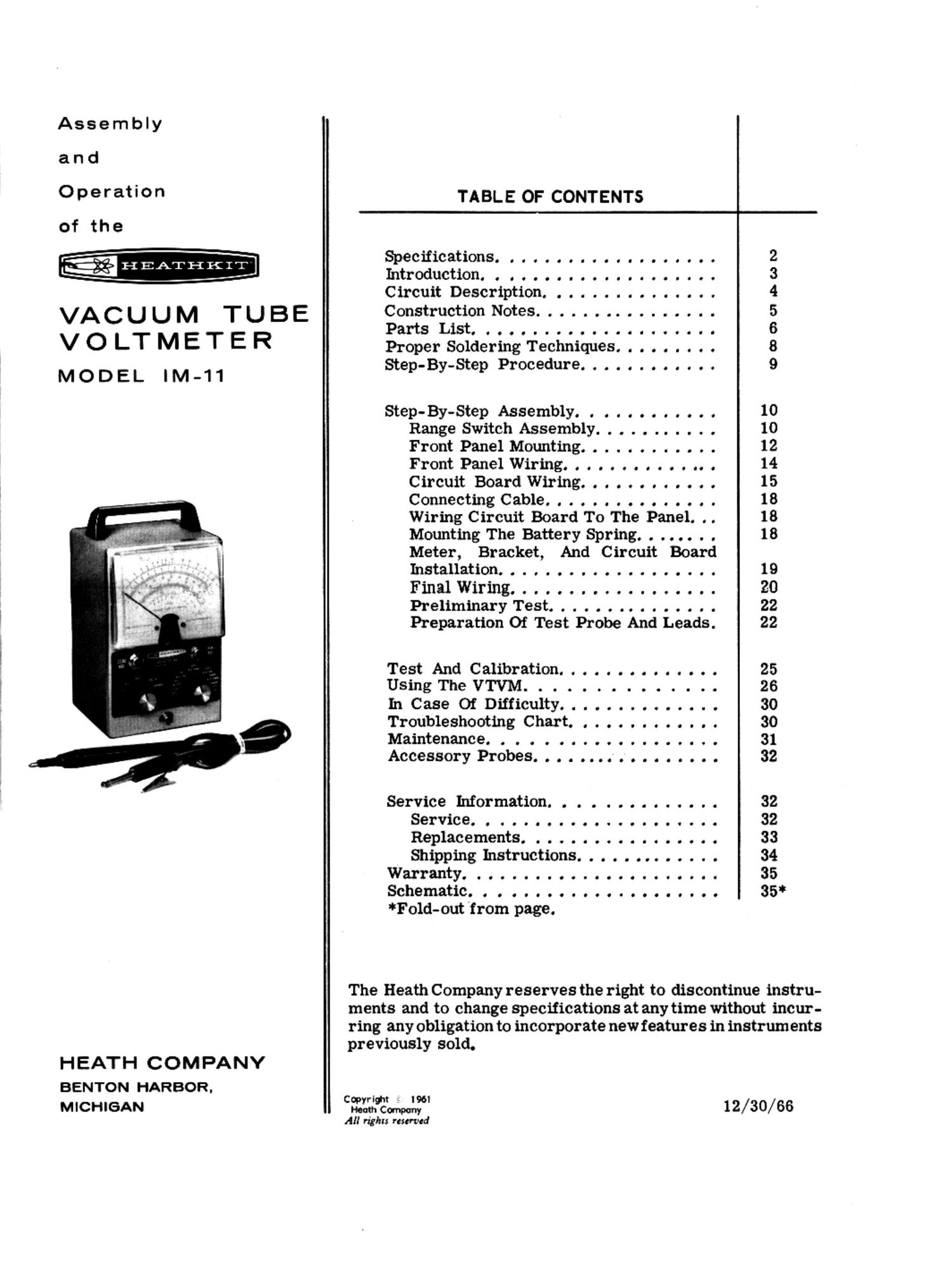
Heathkit IM 11 Manual

This is the 18 pages manual for Heathkit IM 11 Manual.
Read or download the pdf for free. If you want to contribute, please mail your pdfs to info@audioservicemanuals.com.

Page: 1 / 18
left right
Heathkit IM 11 Manual

Extracted text from Heathkit IM 11 Manual (Ocr-read)


Page 1

Assembly

and

Operation TABLE OF CONTENTS I;

of the
Specifications................... 2
mtrOdUCtiondOOOOOCIGOOOIOOIICOO 3
Circuit Description. . .......... . . . 4

B E Construction Notes ................ 5

VACUUM TU PartsList..................... 6

V 0 LT M E T E R Proper Soldering Techniques. . . . . . . . . 8
Step-By-Step Procedure. . . . . . . . . . . . 9

MODEL IM-11

Step-BY'Step Assembly: 0 o o n o o o a o o a 10

Range Switch Assembly ........... 10
Front Panel Mounting. ........... 12
FrontPanelWiring.............. 14
Circuit Board Wiring. . . . . . . . . . . . 15
ConnectingCable............... 18
Wiring Circuit Board To The Panel. . . 18
Mounting The Battery Spring. . . . . . . . 18
Meter, Bracket, And Circuit Board

Installation ..... . . . . . ..... . . . . 19
Finalering.................. 20
Preliminary Test. ............ 22
Preparation Of Test Probe And Leads. 22

Test And Calibration.............. 25

UsingTheVTVM .............. 26
InCase OfDifficulty........ ...... 30
Troubleshooting Chart. . . .. . . . .. . .. 30
Maintenance. . . . . ........ . . . . . . 31
AccessoryProbes................. 32
Service Information. . . . . . . . . . . . . . 32

Service................ ..... 32

Replacements. ..... . 33

Shipping Instructions. . . . . . . . . . 34
Warranty... ..... . 35
Schematic..................... 35*

*Fold-out from page.

The Heath Company reserves the right to discontinue instru-
ments and to change Specifications at any time without incur-
ring any obligation to incorporate new features in instruments
previously sold.

HEATH COMPANY

BENTON HARBOR.

MICHIGAN Cflfiémfi 12/30/66
All rights reserved

Page 2

P4802

SPECIFICATIONS

ElectronicDCVoltmeter-
7W.OOOIOICIOOOCIOI

ll.......

InputResistance

Sensitivity............ .......
Circuit......

I'IIICI.'.........'

my.IICOIOOOOOOOI'OOOOOIOO

Electronic AC Voltmeter -
7 ms Ranges. . .

......OOOIUIOCOUO

7 Peak-to-Peak Ranges ..............

.0...

Frequency Response (5 V range). . .

MwacyICIIOOOIIl.

input Resistance And Camitance. ......

Electronic Ohmmeter -
7 Ranges. ..................... ,.

mrsoossssoosouososu

WSOOOOSO

"COOOOIOOIIIOOI'OOII.

Multipliers......
ChouMIOOCICICIOOOICGCDOCCODI

OOOOIOOOUOCCIOIOCOO

MCCOCCDODCUCOOUICOCICOCO ..... I.

0-1.5, 5, 15, 50, 150, 500, 1500 volts full scale;
up to 30,000 vow with accessory probe.

11 megohms (l megohm in probe) on allranges;
1100 megohms with accessory probe.

7,333,333 ohms-per-volt on 1.5 volt range.
Balanced bridge (push-pull) using twin cm.
1.3% run scale.

0-1.5, 5, 15, .50, 150, 500, 1500 rm: scales
(.853 d pesk-tO-pesk).

0-4, 14, 40, 140, 400, 1400, 4000.
news cpstoI mo (Goonsource).
16% mu scale.

1 megohm shunted by 35 up! (measured at
inputterminale).

Scale with 10 0 center X1, X10, X100, X1000,
XIOK, XIOOK, XIMEG. Names .1 (lino 1000
megohms with internal battery.

4-1/2", 200 no. movement, polystyrene case.

Combined AC-OHMS-DC switching probe, single
jack input for probe and ground connections.

1% precision type.

Printed circuit; etched metal process.

1. - 12AM, twin triode meter bridge.
1 - 6AM, twin diode AC rectifier.

Page 3

Battery.......

DCIO'OIIOOOIOI IIIIII

mmrfiewemmssieeseseeue vvvvv e-
CabinetSizeAndFlnilh...n.......

Net Weight. . . .

'OOIUOUIUOIC'IOOOCUOI.

Page3

141/2 volt 1mm: cell.
105-125 volts, 50/50 cps AC, 10 watts.

7- 3/8" high x 4-11/16" wide x 4-1/8" deep,
charcoal gray.

34/2 lbs.

INTRODUCTION

The HEATHKlT Model lM-ll Vacuum TubeVolt-
meter is intended for use by servicemen, en-
gineers, and maintenance men to make acCurate
measurements or! DC+, DC-, AC rms and peak-
to-peak voltages, plus resistance. The designis
simple and rugged, yet accurate.

The instrument employs vacmimtubes for recti-
fication and amplification on all measurement
junctions to insure good sensitivity andstability
at operation. Precision resistors areusedinthe
voltage divider networks to provide high accu-
racy.

The confusing tangle 0! test leads coming from the
front panel of most VTVMs is eliminated by the
use of a combination AC-OHMS-DC switching test
probe and a single Jack input oonnectioniorboth
test probe and ground leads. The l megohm
resistor in the probe is switched into operation

when the probe switch is set on DC. This iso-
lating resistor allows DC component voltagesto
be measured separately, even when high fre-
quency AC voltages are present atthe test point.

The VTVM has a very high input impedance (11
megohms on DC and 1 megohm shunted by 36
uni on AC). Consequently, the circuit in which
the voltage is being measured will notbe sig-
nificantly loaded by the VTVM. Most nonelec-
tronic voltmeters (VOM) have a much lower in-
put impedance over the most frequently used
ranges oi test voltages. Consequently, when a
VOM is used to measure voltages in high im-
pedance circuits, the indicated voltage willbe
appreciably less than the actual voltage. The
amplifier section of the VTVM also enables the
VTVM to accurately measure much higher re-
sistances than can be measured with a VOM.