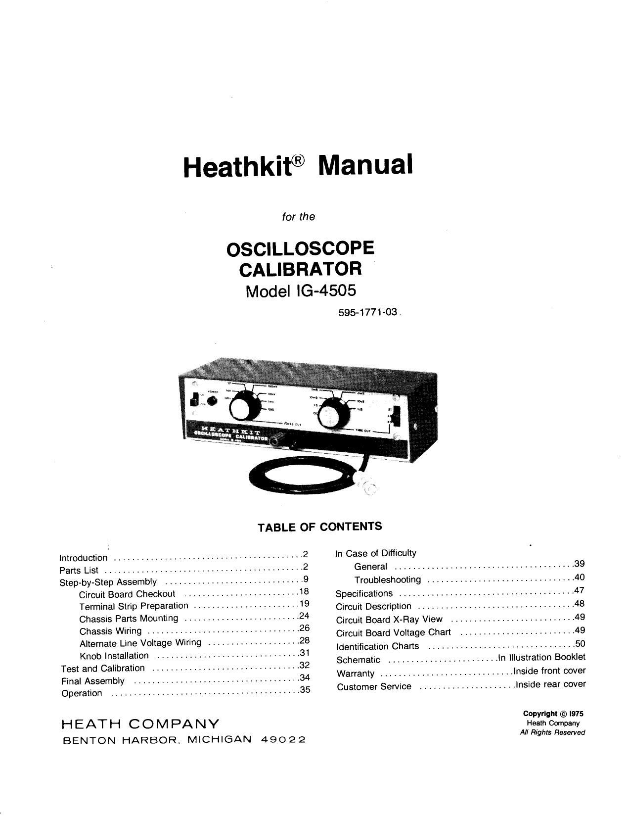
Heathkit IG 4505 Manual

This is the 54 pages manual for Heathkit IG 4505 Manual.
Read or download the pdf for free. If you want to contribute, please mail your pdfs to info@audioservicemanuals.com.

Page: 1 / 54
left right
Heathkit IG 4505 Manual

Extracted text from Heathkit IG 4505 Manual (Ocr-read)


Page 1

Heathkit® Manual

for the

OSCILLOSCOPE
CALIBRATOR
Model IG-4505

595-1771-03 ,

TABLE OF CONTENTS

Introduction .

.................................... 2
Parts List .......................................... 2
Step-by-Step Assembly ....................... 9
Circuit Board Checkout .................. 18
Terminal Strip Preparation , ............. 19
Chassis Parts Mounting ......................... 24
Chassis Wiring ................................. 26
Alternate Line Voltage Wiring
Knob Installation ............................... 31
Test and Calibration ................................ 32
Final Assembly . 34
Operation ......................................... 35

HEATH COMPANY
BENTON HARBOR, MICHIGAN 49022

In Case of Difficulty

General ....................................... 39

Troubleshooting ................................ 40
Specifications . t . ............................... 47
Circuit Description .................................. 48
Circuit Board X-Flay View ........................... 49
Circuit Board Voltage Chart ......................... 49
Identification Charts ................................ 50
Schematic ........................ In Illustration Booklet
Warranty .......................... Inside front cover
Customer Service ..................... Inside rear cover

Copyright © I975
Heath Company
All Rights Reserved

Page 2

Page 2

HEATI-IKIT r

INTRODUCTION

The Heathkit Model lG-4505 Oscilloscope Calibrator is an
accurate, crystalAcontrolled, fast-rise square wave generator.
It provides you with the accurate time and amplitude signals
you need to calibrate Heathkit Oscilloscopes, as well as most
other oscilloscopes.

The time (or period) signals (.5 s to 1 us) are the fast-rise
(less than 4 ns) square waves you need to adjust oscilloscope
sweep speeds, delay line terminations, and high frequency
compensation. A terminated output cable prevents ringing
and assures a good frequency response of the time signal.

The accurate voltage signals (1 mV to 100 V) are used for
oscilloscope vertical calibration and attenuator
compensation.

The Calibrator also serves equally well as a bench standard.
It can be used to calibrate other test equipment or as a signal
source when you build or test experimental circuits.

Refer to the Kit Builders Guide for additional
information on parts identification, tools, wiring and
soldering.

PARTS LIST

Check each part against the following list. Make a check
mark in the space provided (J) as you identify each part.
Any part that is packed in an individual envelope with a part
number on it should be placed back in the envelope after
you identify it until it is called for in a step. Do not discard
any packing materials until all parts are accounted for.

To order a replacement part, always include the PART
NUMBER. Use the Parts Order Form furnished with this kit.
lf one is not available, see Replacement Parts" inside the
rear cover of the Manual. Your Warranty is located inside
the front cover. For pricing information, refer to the
separate "Heath Parts Price List."

Each circuit part in this kit has its own "circuit component
number (R2, C4, 0101, etc.). This is a specific number for
only that one part. The purpose of these numbers is to help
you easily identify the same part in each section of the
Manual. These numbers will appear:

-- In the Parts List;

- At the beginning of each step where a
component is installed;

- In some illustrations;
- On the Schematic;

- In the sections at the rear of the Manual.

Page 12

Page 12

@-

NOTE: The .596 resistors you install in the
following steps may be shaped as shown below.

W R15:90 kfl,.5%.

h) R16: 50005'll5k), 1%.

L"\l R17: 40009. (4 H.196.

l'k) R18: 900 Q, 5%.

( h 319303.596.

(a) R21:9§Z, 5%

lyl R22: 1n, 5%.

lyl' Solder the leads to the foil and cut off
' the excess lead lengths.

NOTE: When you install disc capacitors, do not
push the insulated portions of the leads into the
circuit board holes. This could make it difficult
to solder the leads to the foil.

INSULATION INSULATION
\ /
m

(5 l (39: 10 pF ceramic.

l/l C5: .01 MF ceramic,

: .01 F ceramic.

(/l 03:.01MF ceramic.

NOTE: When you install a tantalum capacitor,
always match the positive it) or dot marked
side of the capacitor with the positive (+) mark
on the circuit board.

Posmvs
\SIGNltl


COLOR
DOT

l3) C8: 15uF tantalum.

(:l C1:10 pF ceramic.

(3 l 62: 47 pF ceramic.

l ) Solder the leads to the toil and cut off

the excess lead lengths.

PICTORIAL 1-3

HEATHKIT5

(K) R13: to m, 1-watt (brown-black-
orange),

NOTE: As you install the following control,
solder the leads to the foil.

R14: 20 kn control.

C6' .01 pF ceramic.

C7: .01 F ceramic.

Yl' 4 MHz crystal.

Solder the leads to the foil and cut off
the excess lead lengths.

Page 15

_HEATHKIT"

For stranded wire, twist the fine strands tightly together and
melt a small amount of solder on the bare wire ends. The
wires are listed in the order in which they will be used.

11 ) Prepare the following wires:

2-1/2" blue
two 2" blue
24/2" blue
two 2 blue
3" black stranded

NOTE: In the following steps, "8-" with a number, such as
(8-3), means to solder the connection. The number
following the "S tells how many wires are at the
connection. (NS) means not to solder because other wires
will be added later.

Connect a 2-1/2" blue wire from switch SW2 lug 1
(8-1) to circuit board hole S(S-1).

(R)

Connect a 2" blue wire from switch SW2 lug 2 (3-1) to

V)
circuit board hole M (S-i ).
(7/) Connect a 2" blue wire from switch SW2 lug 3 (5-1) to

circuit board hole N (31).

(U Connect a 2-1/2" blue wire from switch SW2 lug 4

($41) to circuit board hole V (8-1).

Connect a 2" blue wire from switch SW2 lug 5 (8-1) to
circuit board hole P (S-1 ).

Connect a 2" blue wire from switch SW2 lug 7 (NS) to
circuit board hole NN (34).

Connect one end of a 3" black stranded wire to circuit
board hole R (S-l ). The other end will be connected
later.

0 y. y, :i/4 1 (memes)
1ilslalalsml7ml I l l l I I |

pm pm, . i I I i

O 5 l (cm a a 4 5 6

(«3

Page 15

PREFARE EACH END AS SHOWN

3/4"-~
k-m"
1
l CUT
/\SH D on

lEL
LEAD

<-I/2"

1/4->|

TAKING CARE NOT TO CUT THE SHIELD LEAD,
REMOVE THE OUTER INSULATIONr

_\

(

PEEL OFF THE FOIL.

FOIL

%%D

REMOVE 1/4" OF THE INNER INSULATIONt

Detail 1-6A

3') Refer to Detail 1-6A and prepare the following lengths

of small shielded cable:

2-3/ "
3-1/4"

At the end of a 2-3/4" small shielded cable with the
shield lead, connect the inner lead to switch SW2 lug 6
(54) and the shield lead to switch SW2 lug 7 (NS).
Connect the inner lead at the other end of this cable
to circuit board hole W(S-1).

) At the end of a 3-1/ " small shielded cable with the

shield lead, connect the inner lead to switch SW2 lug 9
(8-1) and the shield lead to switch SW2 lug 7 (8-3).
The free end of this cable will be connected later.

Page 30

CABLE PREPARATION 2. ( ) Wrap the other lead around the inner lead of the
Refer to Pictorial 2-11 in the Illustration Booklet and the shielded cable and solder the connection. Keep
indicated Details for the following steps. the resistor as close to the inner lead as possible.
Cut off the excess lead length.
HEAT
SQEQQVKIANELE 3. ( ) Slide a 1/2 length of small clear sleeving over

Jn-271/2-->/ 1-3/4 the resistor and inner lead as shown.
_ FERRULE
_ _ -m. s .
_l x/ m \i 5 -\/ SMALL

Detail 2-11A

Refer to Detail 2-11A and:

NYLON
SPACER

l. ( ) Slide 3 2-1/2" length of heat shrinkable sleeving Detail 2-11D
onto the free end of the large shielded cable.
Refer to Detail 2-110 and:

2. ( ) Carefully remove 1-3/4" of outer insulation.
1. ( ) Pull the braided shield wires back over the

F-laS/lé resistor to their original position.
8 516
4 F-l/ A I 2. ( ) Slide the BNC nut over the shield wires onto the
\ end of the cable.
INNER
INSULATION 3. l ) Push the braided shield wires back enough to

INSULATlON

expose the end of the inner lead.

Detail 2-118
4. ( l Push the BNC pin (this includes the ferrule and
Refer to Detail 2413 and: the nylon spacer) onto the end of the inner lead.
Solder the pin to the inner lead. To do this,
1. ( ) Push the braided shield wires back over the position the pin 50 the small hole faces upward.
outer insulation. Then hold your soldering iron against the under
side of the pin and apply a M amount of
2. l l Remove 5/16" of insulation from the end of the solder into the small hole. Do not allow solder
inner lead. Then apply a small amount of solder to accumulate on the outside of the pin.
to the bare wire ends.
SOLDER NUT (SHIEE; Sign «CONNEC
3. I ) Measure 1-5/16" from the end of the cable and TOR
carefully remove 1/8 of insulation. v {-5
Uxéég c @122- IQ(®
FERRULE

Detail 2-11E
PLiERlS

Refer to Detail 2-11E and:

DetaIl2-11C 1. ( ) Pull the braided shield wires over the ferrule.
Refer to Detail 2-11C and: Then cut off the shield wires that extend
beyond the sides of the ferrule.

1. ( l Insert one lead of a 51 Q (green-brownvblack),
1/4-watt resistor through the braided shield 2. ( ) Push the connector onto the pin until it seats

wires. against the nylon spacer.
O % 1/2 % 1 (memes) 2 3 4 5 7
[flat 3"HImai I III i I.l l i. l l l i I 1.1 i L luiti l l 1.1
,...,..m1 I , . . I r , . , T T T , . I . I I y i i r l | I I
O 5 1 (CM) 2 a e 5 e 1 a 9 10 1| 12 13 1. 15 16 17