Heathkit IG 1275 Manual

This is the 103 pages manual for Heathkit IG 1275 Manual.
Read or download the pdf for free. If you want to contribute, please mail your pdfs to info@audioservicemanuals.com.

Page: 1 / 103
left right
Heathkit IG 1275 Manual

Extracted text from Heathkit IG 1275 Manual (Ocr-read)


Page 1

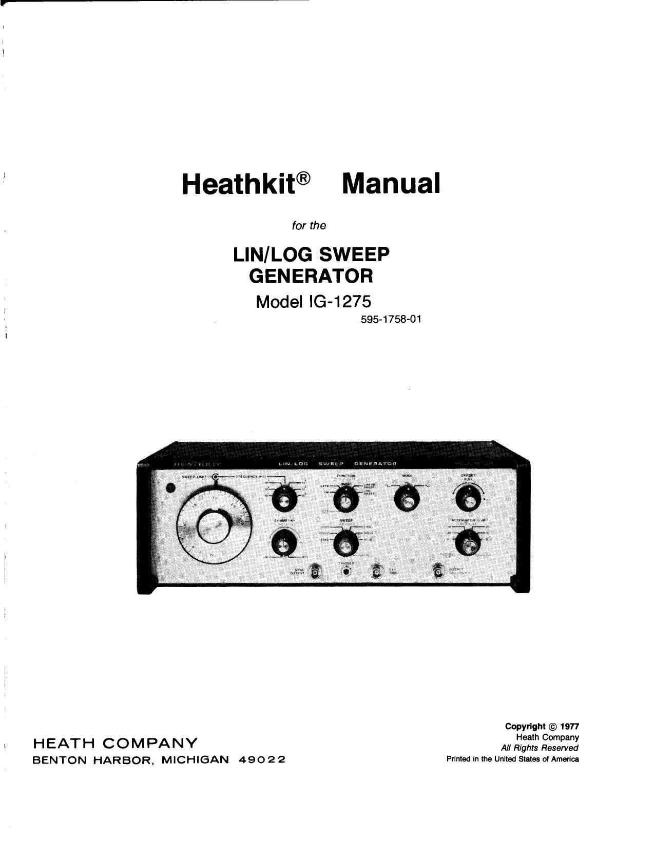
Heathkit® Manual

for the

LIN/LOG SWEEP
GENERATOR

Model IG-1275

595-1758-01

Copyrigm © 1977

Heath Company

HEATH COMPANY Maigmfiesefled
BENTON HARBOR, MICHIGAN 490 2 2 Primed in the United States ofArnerica

Page 6

Page 6

OUTPUT CIRCUIT BOARD

PARTS LIST

Unpack the parts package labeled #1. Check each part
against the following list and the Parts Pictorial (on
Page 1 in the Illustration Booklet). Any part that is
packed in an individual envelope with the part
number on it should be placed back into the envelope
after you identify it until it is called for in a step. Do
not throw away any packing material until all parts
are accounted for.

KEY HEATH QTY. DESCRIPTION CIRCUIT KEY HEATH QTY. DESCRIPTION CIRCUIT
No. Part No. Comp. No. No. Part No. Comp. No.
Resistors (contd.)
A1 1-99-12 1 1 1800 n (brown-gray-red) R263
RESISTORS A1 1-106-12 / 1 3600 n (orangebiue-rod) R248
A1 1-75-12 / 1 3900 n (omnge-white-red) R272
1/ 4-Wati 98'3" A1 1-91-12 d 2 22 m (red-red-orange) R218. R243
NOTES: A1 1-31-12 J 2 es kn, 10% (blue-gray- R257. R259
orange)
1. Resistors are 5% tolerance (fourth band of gold) M M742 J 2 13921433; (brown- R211' R262
unless otherwise noted. Afourth color band of silver _ _ 9 Y
indicates 10% tolerance. Freelsion Reslstors
2. The resistors may be packed in more than one NOTE: Precision resistors are 1/8-watt, 1% tolerance unless
envelope. Open all the resistor envelopes in this otherwise noted. Precision resistors may be marked with a
pack before you check them against the Parts List. manufacturers number in addition to resistance value and
tolerance.
A1 1-125-12 2 22 n (red-red-black) R266, R267 .
A1 1-57-12 / 3 33 n (orange-orange R254, R255. A2 2-53-11 1/ 2 15.8 0 R222, R235
black) R256 A2 2-54-11 4 2 21 0 R223, R236
A1 1-58-12 , 2 47 n (yellow-violet-black) R219. R242 A2 2-55-11 V 2 22.6 (1 R221, F1234
A1 1-115-12 " 1 51 n (green-brown-blaok) R202 A2 2-56-11 v'_ 2 30.1 0 R224, R237
A1 1-102-12 1 68 n (blue-gray-black) R214 A2 2603-1 1/ 2 51.01 a, 1-watt R281, R285
A1 1-70-12 ' 4 1200 n (brawn-red-red) R206, R209, A2 2-57-11 J 2 51.1 11 R225, R238
R227. R241 A2 2-602-1 ./ 2 61.11 a, 1-watt R283, R284

Page 7

-

Page 7

CIRCUIT
M

D215

D207, D214,
D216, D217
D202-0206,
D208, 0209.
D211, D212,
D213

0214

0215

0216

0212, 0213
0207

0206

0204, 0208
0201, 0202,
0200. 0205.
0209

0211

-HEATI-IKIT?
KEY HEATH QTY. DESCRIPTION CIRCUIT KEY HEATH QTY. DESCRIPTION
No. Part No. Comp. No. No. Part No.
1 Resistors (contd.) DIODES - TRANSISTORS
A2 2-601 -11 / 1 71.15 a, 1-watt R277 NOTE: Diodes and transistors are marked for identification in
A2 2-56-11 x." 1 71.5 0 R226 one of the following four ways:
A2 2-329 V 2 96.25 0, 1/2-watt R276, R278
A2 2-66-11 j 1 150 0 R201 1. Part number
A2 2-59-11 V» 1 237 0 R229 2. Type number.
A2 2-328 1 247.5 a. 1/2-watt R282 3. Part number and type number.
A2 2-35-11 \/ 1 254 0 R265 4. Part number with a type number other than the one
A2 22011 1/ 1 453 0 H231 listed.
A2 2-21-11 V01 511 0 R273 v,
A2 2-61-11 V 1 681 0 R232 C1 56-16 2 1 1N751 zener diode (5.1-volt) D201
A2 2-62-11 V 3 1500 0 (1.5K) R217, R233, Cl 56-31 T 1 P818775 zener diode
R246 , (6.8-volt)
A2 2-12-11 yfi 2000 (1 (2k) R205, R247, C1 56-56 4 1N4149 diode
R253, R261
A2 246-12 V 2 2500 .0 (2.5K), 1/4-watt R208, R279 C1 56-86 1 10 F0777 diode
1 A2 2-611-12 4/ 2 3010 n (8.01k), 1/4-watt R204, R207
A2 2-52-11 1 3200 {I (3211) R258
A2 2-49-11 y 1 6110 0 (6.11k) R251
A2 2-613-12 l/ 1 00 0 (9k), 1/4-walt R249 02 417-224 1 MPSU05 transistor
A2 2-41-11 I 2 13 k0 R215, R244 C2 417-225 I 1 MPSUSS transistor
03 417-269 \/ 1 8605282 transistor
I C4 417-879 / 2 2N3251 transistor
i Other Resistors 05 417-074 1 1 2N3906 transistor
1 05 417-875 V 1 2N3904 transistor
A3 1-135 / 2 6.8 fl. 1/2-watt, 5% R269, R271 06 417-235 1/ 2 2N4121 transistor
1 ~ , (blue-gray-gold-gold) 06 417-801 1/ 5 MPSAZD transistor
l M 1-41-2 \/ 3 47 fl, 2-watt, 5% R268, R274,
I (yellow-violet-blam) R275
07 417-877 ./ 1 CA3018A transistor array
1 CAPACITORS

NOTE: Capacitors can be marked in many different ways.

CONTROLS - SWITCHES - INDUCTOR

EXAMPLE: 2, 22k, 22M, 22 FF. However, the Pans List and 01 10-917 / 2 200 0 control R226. R239
' installation instructions will always use 14F (or pF for very small D1 10-295 V 2 750 (I control R216, R245
I value capacitors). D1 10-906 \/ 1 1000 m (1 k) control R200
. D1 10-1070 \/ 1 2500 n (2.5 k) control R252
B1 20-104 1 130 pF mica 0212 D1 10-365 y 2 50 kt! control R212, R264
B1 20-108 0 1 200 pF mica 0211 02 19-724 -/ 1 1000 0 (1k) control/switdi R213/sw202
52 21-30 V' 1 3.3 pF ceramic 0208 03 63-1274 y 1 Rotary switch swzo1
32 21-176 ,/ a 0.01 11F ceramic 0201-0206. D4 40-582 v' 1 62 pH indudor (blue-red- L201
0210, 0213 black)
as 27-47 V' 3 0.1 MP Mylar" 0214, 0215,
C216
, 34 31-71 1/ 1 3.2-18 pF trimmer 0207 HARDWARE
(blue dot)
54 31-83 V 1 2-6 pF trimmer 0209 E1 250-52 V 2 4-40 x 1/4" screw
(red dot) E2 252-2 1/ 2 440 nut
E8 252499 1/ 1 Small control nut
E4 253-2 v' 2 Fiber shoulder washer
'Registered Trademark, DuPont Corp. E5 254-14 ./ 1 Small cormol Iockwasher
0 y. 72 s/ 1 (mm-1:5) 2 3 4 6 6 7
Lu'iaelmlisl 1 1.1 I I 1 I 1 | I I 1 1.1 I 1 I I . I 1.1 1. I
l" I 1 I ' l ' I I l l ' I ' T ' I ' I I I I I I '
0 5 1 (our) 2 a 4 Is 6 7 e 0 10 u 12 1e 12 15 1e 17

Page 44

Page 44

CHASSIS

PARTS LIST

Check all the remaining parts in the Final Pack
against the following Parts List and the Parts Pictorial
(on Page 6 in the Illustration Booklet).

KEY HEATH QTY. DESCRIPTION CIRCUIT KEY HEATH QTY. DESCRIPTION CIRCUIT
No. Pan No. Comp. No. No. Part No, Comp No.
RESISTORS CONTROL -- SWITCHES
A1 1-8112 1 27 k0, 1/4-watl, 5% R404 C1 12-165 V 1 Dual 5000 (2 (5k) control R5/ F16
(red-violet-cwange) C2 19-723 v 1 so kn control with switch FH/SWS
A2 2~56-12 \/ 1 1000 .0 (1 k), 1/4-wan, 1% R2 CS 63-1272 V, 1 Rotary switch SW1
precision C4 63-1270 « 1 Rotary switch with dual SW2/R3/
A2 2-267 l/ I 16 k0, 1/2-wan, 1% R403 / 33 kn. control R4
precision CS 60-54 1 120-240" slide switch SW4
A2 2-268 \/ 1 24 k0. 1/2~wau, 1% R402 06 60-608 / 1 LowNof slide switch SW5
precision C7 64-31 1 Pushbunon switch SW6
A2 2-269 / 1 48 kn, 1/2-wa11. 1% R401
premsron
CAPACITORS HARDWARE
81 21-71 1/ 1 0.001 1.1: (1000 pF), C1 #4 Hardware
114 kV ceramic /
82 27-68 \/ 1 0.0033 MF (3300 pF) 0401 D1 250-156Q) 1 4-40 x 1/8 setscrew
/ Mylar D2 250-213 , 9 4-40 X 5/16 screw
32 27-42 1 0.0068 MP (6800 pF) 0402 D7 252-2 1/ / 8 4-40 nm
Mylar D18 254-9 v 9 #4 lockwasher
132 27-106 V 1 0101 uF Mylar 0403 024 255-151] 1 4-40 x 13/11:w tapped spacer

Page 53

(

(

(

]

l

]

(E

LOCKWASHER iii}

l
LARGE (\3 /<0
SOLDERLUG Q 45
I \L
LARGE
PLASTIC 6'9
SHOULDER
WASHER l

LAROE
PLASTIC
SHOULDER §@)
WASHER |
go
BNC
CONNECTOR E
\

,5 Detail 4-2D

Refer to Detail 4-2D and mount 3 ENG connector
at location CC Use the hardware supplied with
the connector, two large plastic shoulder
washers, and a large solder lug. Make sure the
shoulder of each plastic washer fits into the
panel opening and the solder lug is positioned
as shown in the Pictorial before you tighten the
nut. Then tighten the nut. Bend the small end of
the solder lug cut away from the panel to an
angle of approximately 45 degrees.

In a like manner, mount 3 ENG connector at
location CD.

In a like manner, mount a BNC connector at
location CE.

[

Page 53

RUBBER
GROMMET

]

CONTROL
MOUNTING


CONTROL
LOCKWASHER

1 'r-

w
«4, :

PLATE

#4LOCKWASHER/

QCONTROL
NUT

4-40x13/16"/ msfigfiffis
THREADED
SPACER
Detail 4-2E

Refer to Detail 4-2E and insert a rubber grommet
into the large slot in the control mounting plate.

Refer to Detail 4-2E and position the mounting
plate so it matches the illustration. Then mount
a 4-40 x 13/16" threaded spacer with a 4-40 x
5/16" screw and #4 lockwasher, Position the
spacer in the center of the slot. You will realign
the spacer in a later step.

R5/R6: Refer to Detail 4»2E and mount the dual
control [#12-165) to the control mounting plate
with a control lockwasher and control nut. Be
sure to fit the control locating tab into the slot
provided in the plate. Then press the brass
bushing onto the inner shaft of the dual control
until the bushing is even with the end of the
shaft.

Page 78

Page 78

( ) Turn the front panel SWEEP LIMIT control
fully counterclockwise.

[ ) Turn the FUNCTION switch to BURST.

[ ) Adjust the oscilloscope reference ground line to
the center graticule line [oscilloscope DC
coupled].

( ] Turn the front panel TRIG LEVEL control to the
center of its rotation.

( ) Turn the SWEEP switch to 100 MS.

( ] Turn the front panel SWEEP VARIABLE control
to the center of its rotation.

[ ) Turn the MODE switch to the triangle-wave
symbol.

( ) Connect the oscilloscope to the front panel
OUTPUT connector.

fiflEAII-IKIT

( ) Adjust the front panel TRIG LEVEL control for a
waveform that contains two cycles and a base
line.

[ ) Adjust BASE LINE control R361 to position the
signal base line on the center graticule line of
the oscilloscope.

[ ) Turn the front panel TRIG LEVEL control to
AUTO TRIG.

[ ) Turn the front panel SWEEP VARIABLE control
to CAL.

[ ) Disconnect all of the test equipment.

This completed the Calibration. If you are perform-
ing Initial Tests and Calibration" for the first time,
proceed with Generator Tests and verify the opera-
tion of the remaining circuits that require no calibra-
tion. If you were recalibrating the Generator, turn it
off, disconnect the line cord plug, and reinstall the
top, bottom, and side panels.

GENERATOR TESTS

These tests are to verify that the remaining Generator
circuits that were not examined during calibration
function properly. Do not change the Generator
switch and control settings from the previous page
unless you are instructed to do so.

( ) Turn the FUNCTION switch to CW.

( ] Connect the oscilloscope to the front panel
OUTPUT connector. You should observe a 30
kHz. ZO-volt peak-to-peak [minimum] triangle
waveform [high impedance oscilloscope
probe).

[ ) Connect the oscilloscope to the front panel
SYNC OUTPUT connector. You should observe
a 30 kHz square wave at 1.5 volts peak-to-peak,
minimum.

[ ] Connect the DC voltmeter to the rear panel
ANALOG OUTPUT connector. You should
measure approximately +6 volts. Turn the front
panel FREQUENCY control clockwise. As the
indicated frequency decreases. the voltage de-
creases.

( ] Turn the front panel FREQUENCY control to
3.0

( ] Connect the oscilloscope to the front panel
OUTPUT connector. Be sure to properly termi-
nate the cable or use a high impedance oscillos-
cope probe.

{ ) Turn the MODE switch to the square-wave
symbol.

[ ] Adjust the ATTENUATOR switch and control
for a 5-volt peak-to-peak signal.