Heathkit IG 102 Manual

This is the 10 pages manual for Heathkit IG 102 Manual.
Read or download the pdf for free. If you want to contribute, please mail your pdfs to info@audioservicemanuals.com.

Page: 1 / 10
left right
Heathkit IG 102 Manual

Extracted text from Heathkit IG 102 Manual (Ocr-read)


Page 1

Page 20

HEATHIiIT

CALIBRATION

Before starting the Generator calibrationy care-
fully study the operation of each control and
switch as described in Figure 2 on Page 23.

An AM radio is needed to calibrate bands Ay
B, C, D, and E. The tuned circuit and component
parts for band F have been preadjusted at the
factory. If additional accuracy is desired, an
FM radio must be used to calibrate band F.

BANDS A THROUGH E
( ) Turn the BAND switch to band B.

( ) Turn the Modulation switch to EXT MOD.

( ) Turn the FINE ATTEN control fully clock-
wise.

( ) Set the COARSE ATTEN switch at HI.

( ) Connect the shielded output cable to the
Generator RF OUT connector. Place the
free end of this cable near the loop or
antenna lead of the AM radio, but do not
connect it directly to the radio.

( ) Turn the Generator and AM radio on. Allow
the Generator and radio to warm up for 15
minutes so all components will reach nor-
mal operating temperature.

The following procedure will be usedto calibrate
the Generator.

First, a signal of known frequency is tuned in on
the AM radio. Then the dial pointer of the
Generator is set to the exact frequency of the
station the radio is tuned to. The RF oscillator
is then tuned to the same frequency as the radio
station by adjusting it until a zero beat is heard
in the radio.

This zero beat is the signal that is created by
the beating together of the oscillator signal and
the station signal in the radio, When the beat is
heard, it starts out as a high pitchedtone, which
gradually changes as the beat frequencybecomes
lOWer until the tone becomes very low pitched,
Once the zero beat point is passed, the tone
gradually increases in pitch until it can no
longer be heard.

At these frequencies it is often hard to get a
complete zero beat (no sound at all) between the
signals. Often, a low pitched tone or a slow
popping sound will be as close as you will
be able to come to a complete zero beat. The
output level of the Generator should be justhigh
enough to give a clear beat sound; do not
set the Generator output level higher than
necessary.

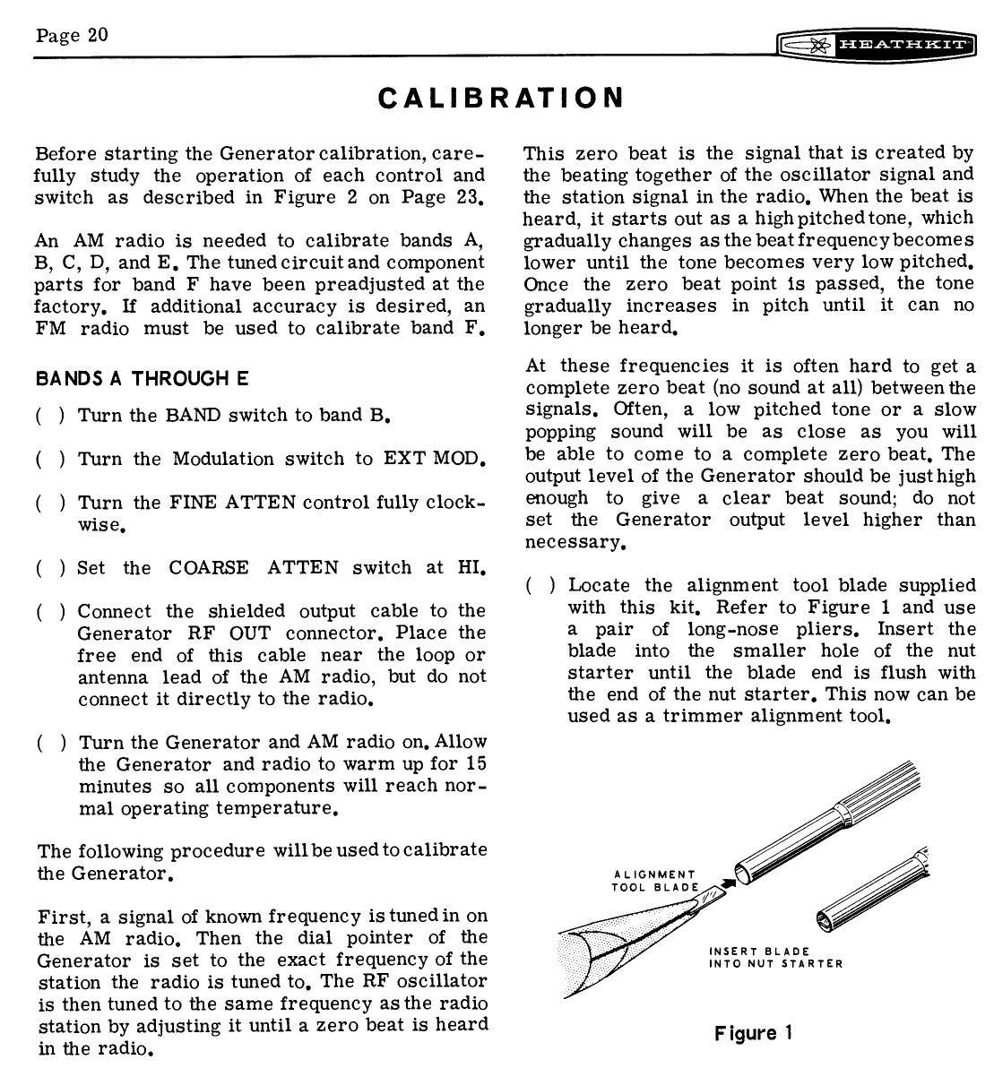
( ) Locate the alignment tool blade supplied
with this kit. Refer to Figure l and use
a pair of long-nose pliers. Insert the
blade into the smaller hole of the nut
starter until the blade end is flush with
the end of the nut starter. This now can be
used as a trimmer alignment tool.

ALIGNMENT
Toon. my;

INSERT BLADE
INTO NUT STARTER

Figure I

Page 2

-HEATHKIT

Page 21

( ) Referring to Pictorial 7 (Page 18) andusing
the trimmer alignment tool, preset trimmer
capacitor C6 until the top of the adjustment
screw is 1/2" above the chassis.

( ) Tune the AM radio to a station of known
frequency between 800 and 1000 kc. The
frequency of this station should preferably
be one whose frequency falls directly on one
of the calibration points on the dial, such as
800 kc, 850 kc, 900 kc, or 1000 kc.

( ) Turn the dial pointer on the Generator to
the place on the dial that indicates the exact
frequency of the station the radio is tuned to.

( ) Adjust trimmer capacitor C6forazero beat
in the radio. Use the FINE ATTEN and
COARSE ATTEN controls to set the output
level of the Generator just high enough to
give a clear zero beat in the radio.

This completes the calibration of bands A
through E. Turn off the AM radio.

The frequencies, for bands Athrough E, were ad-
justed with trimmer capacitor C6. This was pos-
sible because the adjustment slug, for each coil
on these bands, was accurately adjusted at the
factory. A slight improvement in accuracy could
be obtained if the slug in each coil was adjusted
by Zero beating the Generator signal with an accu-
rate frequency standard. An accurate frequency
standard could be obtained by tuninga communi-
cations receiver to a WWV frequency such as
2.5 mc, 5 me, 10 mc, etc., (National Bureau of
Standards). Standard frequencies can also be
obtained from a precision laboratory generator
(with an accuracy of at least 1%), in conjunction
with an oscilloscope to indicate the zero beat.
If the coil slugs are adjusted, each band should
be adjusted near the low end of the dial. A coil
alignment tool, for adjusting the coil slugs, is
supplied with the kit.

BAND F

To calibrate band F to obtain additional accu-
racy, you must use an FM radio.

( ) Turn on the FM radio and tune it to a
station between 88 mc and 100 me.

A

Set the BAND switch to band F, and turn
the dial pointer to the frequency of the FM
station.

( ) Turn the Modulation switch to INT MOD/AF
OUT.

A

Connect the output cable of the Generator
to the antenna terminals of the FM radio.

( ) Turn the Generator dial pointer back and
forth and listen for the 400 cps tone modu-
lation in the FM radio. This 400 cps tone
will be weakest at the correct frequency,
and it will be louder on both sides of this
frequency.

( ) Turn the Generator dial pointer to theplace
where the 400 cps tone is weakest. If the
dial indicator points to a frequency lower
than the station frequency, gently squeeze
together the turns of coil F. Then retune
the dial pointer to the weakest 400 cps
tone. Repeat this procedure until the cor-
rect frequency is indicated onthe Generator
dial. See Pictorial 5 to identify coil F. If
the dial pointer indicates a higher fre-
quency than the station frequency, the
turns of coil F should be spread apart
slightly.

This completes the calibration of band F.

Page 7

Page 32

When switch S3 is in the External Modulation
position, tube V2A is used to amplify the external
modulation signal that is connected to the Ex-
ternal Modulation In connector. This signal
is coupled through capacitor Cll to control R4,
and then to the grid of tube VZA. The signal
is then amplified by tube VZA and coupled
through capacitor 017 and resistors R7 and R8
to the grid of tube VZB.

A MPLIFIER AND MODULATOR

The RF and AF signals are coupled to the grid
of tube VZB. Resistors R7 and R9 keep the
AF signal from overdriving the grid of tube
V2B and also determine the modulation level.
From the plate of tube VZB, the modulated

-I-IEATHKIT

RF signal is coupled through capacitor C20,
Fine Attenuator control R12, Coarse Atten-
uator switch S4, and capacitor C22 to the RF
Output connector.

POWER SUPPLY

B+ voltage is supplied to all stages of the Gen-
erator by a half-wave rectifier circuit con-
sisting of diode D1. Resistor R17 with capac-
itors C25A and C25B provide filtering of the B+
voltage.

Filament voltage is supplied to the filaments of
all tubes and the #47 lamp by a 6.3 volt AC
winding on power transformer T1.