Heathkit ID 5001 B Manual

This is the 70 pages manual for Heathkit ID 5001 B Manual.
Read or download the pdf for free. If you want to contribute, please mail your pdfs to info@audioservicemanuals.com.

Page: 1 / 70
left right
Heathkit ID 5001 B Manual

Extracted text from Heathkit ID 5001 B Manual (Ocr-read)


Page 1

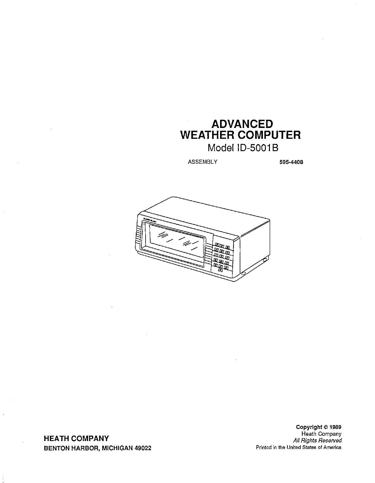
ADVANCED

WEATHER COMPUTER
Model lD-5001 B
ASSEMBLY 595-4408

Copyright © 1989

H h C
HEATH COMPANY All H2213 3:23:33:

BENTON HARBOR, MICHIGAN 49022 Printed in the United States of America

Page 2

Page II ' ®
Heathklt
Table of Contents
INTRODUCTION ........................ III POWER SUPPLY CIRCUIT BOARD
Parts List ............................... 2-1
SPECIFICATIONS ........................ V StepBy-Step Assembly .................... 2-4
UNPACKING INSTRUCTIONS ........... VIII MAIN CIRCUIT BOARD
Parts List ............................... 3-1
ASSEMBLY NOTES ...................... IX Step-By-Step Assembly .................... 3-4
DISPLAY CIRCUIT BOARD CHASSIS
Parts List ............................... 1-1 Parts List ............................... 4-1
Step-By-Step Assembly .................... 1-3 Step-By-Step Assembly .................... 4-4
Boom Assembly ........................ 4-14

Taped Components Chart .................. A-l

Page 49

Page 4-8

Heathkit

Position 7-hole socket S405 with the slots facing up
and insert the prepared wires into the holes as follows:

( , Brown wire in hole 1.
( )/ Red wire in hole 2.
NOTE: Hole 3 is not used.
( )/ Yellow wire in hole 4.

( )/-heen wire in hole 5.

( )/'/Blue wire in hole 6.

( )» Violet wire in hole 7.

( ) Insert a polarizing plug in hole 3 of the 7-hole
socket.

( a/Slide a small RF core over the free end of each of
the 7-hole socket assembly wires.

Connect the 7-hole socket assembly wires to terminal

wry/as follows:

(,x) glue wire to lug 2 (S-2).
( 9/yi'olet wire to lug 3 (S-2).
(3/:Green wire to lug 4 (S-2).
(3/ Yellow wire to lug 5 (5-2).

Connect the remaining socket assembly wires to tenni-
nal strip' D as follows:

( )/ Brown wire to lug 2 (5-2).

(a/ Red wire to lug 5 (5-2).

( )/ /Move the RF cores near the terminal connections.

( ) Check the lugs at terminal strips B, C, D, and E and
make sure that all of the connections are properly
soldered. There should be no unsoldered connec-
tions.

NOTE: When you connect component leads to tenni-

nal stripsG and H, make mechanically secure connec-
tions (see inset drawing #4). To make a connection

mechanically secure, form a hook in the bare end of the
lead; then hook the bare end through the lug and crimp
«it securely in place.

( )\Connect the green line cord lead to solder lug J (S-

b

( ) Conn t the black line cord lead to terminal strip

( ) Connect the
G lug 4 (NS).

( ) Position power trans nner T1 with the black

ONLY THE INSTRUCTIONS THA AGREE
WITH THE LINE VOLTAGE IN YOUR BEA.

120 VAC Wiring
Refer to Detail 4-3A for the following steps.

( ) Connect the black and black-green leads to
the bottom eyelet of lug 4 of terminal strip
H (8-2) as shown in the inset drawing.
Form a small loop in the bare wire ends to
make a mechanical connection.

( ) Similarly, connect the black~yellow and
black-red leads to the bottom eyelet of lug
2 (8-2) of terminal strip H. Make sure the
bare wires do not contact the terminal strip
mounting hardware.

240 VAC Wiring
Refer to Detail 4-3B for the following steps.

( ) Connect the black transformer lead to the
bottom eyelet of lug 4 (S- 1) of terminal
strip H. Form a small loop in the bare wire
end to make a mechanical connection as
shown in the inset drawing.

Page 59

Page 4-18

Heathkit"

Refer to Pictorial 4-13 for the following steps.

In the following steps, you will mount the wind cup
circuit boards in one of the top housings.

( ) Place one of the top housings upside down next to
the bottom housing.

( ) Place the WCT board in the housing component
side up. Then fasten the board with four 6-32 x
9/16" spacers and four #6 SSTL lockwashers. Use
a pair of pliers to tighten the spacers.

( ) Position 'an encoder disc with the painted side
down and mount it on the shaft with a 6-32 SSTL
nut, 21 #6 SSTL lockwasher, and a #6 SSTL flat
washer. Hold the slotted end of the shaft with a pair
of pliers while you tighten the nut. Be careful not
to damage the flat end of the shaft with the pliers
and make sure that the #6 flat washer is flat against
the shaft step.

( ) Place the WCB circuit board component side
down and with Q601 opposite D601 on the WTC
board. Then fasten the board with four 6-32 x l/ "
SSTL screws.

Refer to Pictorial 4-14 for the following steps.

( ) Check the wires coming from each board to make
sure they are not touching the disc. Then turn the
top housing right side up and place it on the bottom
housing. Make sure none of the wires are pinched
between the two housings. Now, rotate the top
housing until the notch lines up with the tab on the
bottom housing.

( ) Spin the shaft with your finger to check for any
noise of wires rubbing on the disc. Then fasten the
housings together with three #4 x l SSTL self-
tapping screws.

( ) Position the wind cup as shown. Then line up the
flat in the cup with the flat on the shaft and install
the cup. Fasten it with a #6 rubber washer and a 6-
32 cap nut.

( ) Place the end cap with the hole pointing down and
push it on the end of the boom.

WIND VANE WIRING

Refer to Pictorial 4-15 for the following steps.

Locate the two sensor circuit boards that are marked
WVT and WVB.

WVT Circuit Board

Position the W V I board as shown and connect the wires
in the following steps.

( ) White to hole E.
( ) Black to hole F.
( ) White/red to hole G.

( ) White/brown to hole L.

WVB Circuit Board

Position the WVB board as shown and connect the wires
in the following steps.

( ) Red to hole B.

( ) Brown to hole A.
( ) Blue to hole H.

( ) Yellow to hole D.
( ) Orange to hole C.
( ) Green to hole W.

( ) White/orange to hole K.

Refer to Pictorial 4-16 for the following steps.

In the following steps, you will mount these two circuit
boards in the remaining top housing.

( ) Place the top housing upside down next to the
bottom housing.