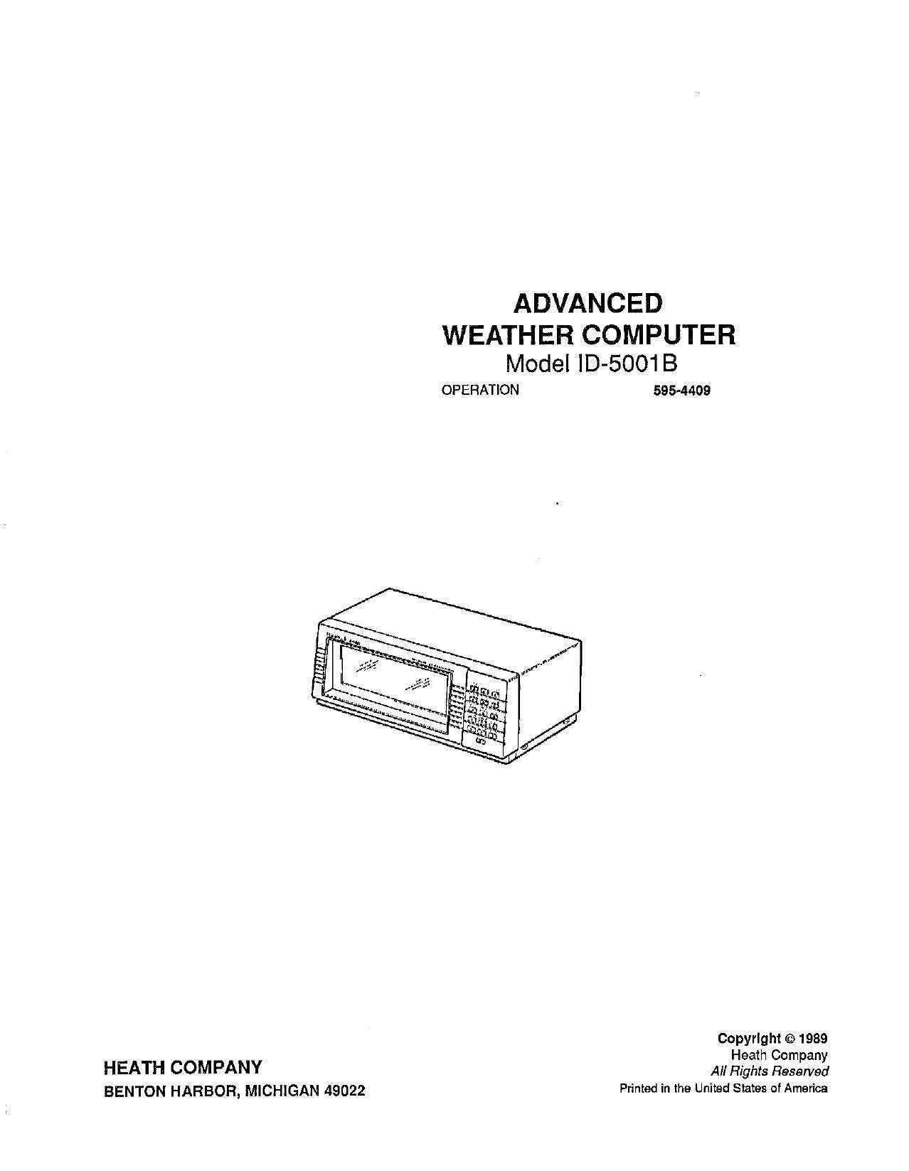
Heathkit ID 5001 B Manual 2

This is the 49 pages manual for Heathkit ID 5001 B Manual 2.
Read or download the pdf for free. If you want to contribute, please mail your pdfs to info@audioservicemanuals.com.

Page: 1 / 49
left right
Heathkit ID 5001 B Manual 2

Extracted text from Heathkit ID 5001 B Manual 2 (Ocr-read)


Page 1

ADVANCED

WEATHER COMPUTER
Model ID-5001 B
OPERATION 595-4409

Copyright © 1989

H h C
HEATH COMPANY All HZ? £21533

BENTON HARBOR, MICHIGAN 49022 Printed in the United States of America

Page 2

. o
P39 . Heathklt
Table of Contents
SPECIFICATIONS ....................... 1-1 Fog Indicator ............................ 5-5
Display Intensity Setup .................... 5-5
INITIAL TESTS ......................... 2-1 Display Viewing Angle .................... 5-5
Display Test ............................. 5-5
CALIBRATION Erroneous Display Readings ................ 5-6
Barometric Pressure ....................... 3~1
Temperature ............................. 3-5 IN CASE OF DIFFICULTY
Visual Tests ............................. 6-1
INSTALLATION Troubleshooting Chart ..................... 6-2
Temperature Sensors ...................... 4-1
Wind Sensor Assembly .................... 4-1 CIRCUIT DESCRIPTION ................. 7-1
Cable Routing ........................... 4-1
Cable Connections ........................ 4-2 SEMICONDUCTOR IDENTIFICATION ..... 8-1
Lightning Protection ...................... 4-2
QUICK REFERENCE GUIDE ............. A-l
OPERATION
Setting the Time and Date .................. 5-1 CIRCUIT BOARD X-RAY VIEWS
Rate Functions ........................... 5-2 . ............. (Illustration Booklet, Pages 13-17)
Min/Max Functions ....................... 5-4
Units Setup .............................. 5-4 SCHEMATIC ....................... (fold-in)
Wind Speed ............................. 5-4
Wind Direction .......................... 5-5 WARRANTY ................ inside front cover
Windchill ............................... 5-5

CUSTOMER SERVICE ........ inside rear cover

Page 7

Heathkit

Page 1-3

RAIN GAUGE
Displays .............................

Units . ..............................

Repeatability .........................
Memory .............................
Operating Temperature .................
Dimensions ...........................

Weight ..............................

RELATIVE HUMIDITY

Displays .............................

Measurement Range ....................
Accuracy @ 25°C (77 '1) ................

Response Time to 90% value at 25°C/77"F . .

Memory .............................

Operating Temperature Range ............

GENERAL

Power Requirements ...................

4 digit.

Inches to 99.9, centimeters to 250, with automatic decimal
point adjust.

:|:l count in 10 for a l-inch-per-hour rain fall.
Change in last hour or 24 hours.

Rain unit 0°C to 50°C (32°F to 122°F).

Rain unit 9.0" diameter x 9.6" high .

Rain unit 1.6 lbs. (.7 kg).

Indicates indoor and outdoor relative humidity 2-digit
readout and rising and falling indicators. Rate of change
per hour.

10% - 90% relative humidity.
$10 counts.

From 10% to 43% relative humidity in less than 3 minutes.
From 43 % to 90% relative humidity in less than 5 minutes.

High and low since cleared, change in last 24 hours.

0°C to 50°C (32°F to 122°F).

120/240 VAC, 50/60 Hz; approximately 19 watts. Provi-
sion for connection to an external 6- to 9-volt battery
which can supply approximately 30 mA to retain memory
contents and maintain clock and rain gauge operation dur-
ing power interruptions. (This feature suspends all other
functions during the interruption and draws current from
the battery only during the interruption.)

Page 10

Page 2-2

Heathkit

( ) Connect the line cord plug to an appropriate AC
outlet.

Touch the voltmeter's positive lead to the following pins
at power supply circuit board plug S303:

( ) Pin 6 for a reading of +5.5 VDC.

( ) Pin 7 for a reading of +5 VDC.

( ) Pin 8 for a reading of -15 VDC. NOTE: Inter-
change the test leads if your voltmeter does not
have the auto-polarity feature.

( ) Pin 9 for a reading of +15 VDC.

( ) Remove the line cord plug from the AC outlet.

( ) Disconnect the voltmeter leads and set it aside.

( ) Reconnect socket S303 to the power supply circuit
board.

OPERATIONAL TESTS
NOTE: You may use the temperature sensor cables at
their present lengths. However, if you want to shorten
one cable, or both (because of where you are going to
install your Weather Computer), do it now before you
perform the "Calibration." Refer to the "Installation"
section on Page 4~1, if necessary.

Refer to Pictorial 3-4 and temporarily connect the wires

at the free end of the outdoor temperature sensor (long-

est cable) to the connector strip labeled OUTDOOR

TEMPERATURE as follows:

( ) Silver wire to GND.

( ) White wire to WHT.

( ) Black wire to ELK.

Refer to Pictorial 3-4 and temporarily connect the wires

at the free end of the indoor temperature sensor (shortest

cable) to the connector strip labeled INDOOR TEM-
PERATURE as follows:

( ) Silver wire to GND.

( ) White wire to WHT.

( ) Black wire to BLK,

Refer to Pictorial 1-3 for the following steps.

( ) Connect the line cord plug to an appropriate AC
outlet; you should observe the following condi-
tions:

The green front panel LED will light.

The unit may "beep."

After approximately 10 seconds, the fluorescent
lamp will light.

You should observe the following display indications:

A compass rose (wind direction) display
Wind Speed: 0

Random Inside and Outside Temperature
CF) readings

Barometer 1N (inches): random reading
Hours

Minutes

Seconds

AM

Day

Month

Note that the Hours digits will flash when you first apply
power, and will continue to flash for approximately one
minute. After this period, the clock circuit will auto-
matically begin to keep time, starting at 12:00.00 AM.
When any of the clock digits are flashing, it means that
that function is in the "set" mode.

NOTES:

1. Whenever you are instructed to press two key-
board keys, be sure that both keys are depressed at
the same time.

2. If the hours digits stop flashing before you are able
to continue with the following steps, press the
TIME SET and ENTER keys and then the TIME
SET key again. The hours digits will then begin to
flash once more.

( ) Press ENTER and the minutes will begin to flash.

( ) Press ENTER and the seconds will begin to flash.

Page 26

Page 5-2

Heathkit

After you enter the seconds, the AM indicator will flash;
you can then set the time display for either AM, PM, or
24-hour format. (The 24-hour format modes do not
display AM or PM.) Press the UNITS key to go between
AM and PM; press the 24HR key to go between the 12-
hour and 24 -hour formats. After you set the desired
mode, press ENTER to enter this mode into the Weather
Computer.

As soon as you enter the AM-PM information, the
Weather Computer will go into the standard or daylight
saving time set-up mode. Initially, it should be in stan-
dard time as indicated by a flashing S. Press the UNITS
key to go between standard and daylight saving time,
where daylight saving time is indicated by a flashing D.
After you set the desired mode, press ENTER to enter it
into the Weather Computer's clock. NOTE: The D or S
is never displayed, except when you are in the D-S set-
up mode.

The date functions are called up next (this occurred
when you pressed ENTER to set D or S). The order of
setup is: month, day of month, and year. The year is not
normally displayed; however, it is written over the day
of month when you set the year. Enter this information,
followed by ENTER, as you did when you used the digit
keys to set the desired time. After you enter the year, the
Weather Computer exits the clock set-up mode.

You can manually enter the time/day set-up mode any-
time by first pressing the TIME SET and ENTER keys;
then release these keys and press the TIME SET key
again. If you just press the TIME SET and ENTER keys
once, however, you enter a simple minute-update
mode, where the seconds go to 00 when you press the
ENTER key. If the displayed seconds are 30 or less
when you press ENTER, the minutes remain un-
changed. If the displayed seconds are greater than 30
when you press the ENTER key, "1" is added to the
minutes. Then the clock will exit the set-up mode and
start keeping time again.

RATE FUNCTIONS

When you press the RATE key, the rate value displayed
for wind speed or rain reflects the change that has oc-
curred since the value recorded exactly one hour earlier.
The wind speed rate is based upon the average wind
speed value. The rate values for barometric pressure,
humidity, and temperature are based on the time be-

tween successive changes; however, the values are cal-
culated and displayed based on the corresponding
hourly rate. If you press the 24HR key, the rate value
shown reflects the change that has occurred since the
value recorded exactly 24 hours earlier for the various
displays.

The rate displays will be held as long as you keep the key
depressed, and will revert back to the normal display as
soon as you release the RATE or 24 HR key. If the
Weather Computer does not have enough data to base a
rate upon, such as on initial powerup, two dashes (--)
and two "arrow heads" (A for an increase, or V for a
decrease) will be displayed to indicate that no rate is yet
available. The two dashes will be displayed for up to
three hours after power is turned on. After this time, the
current rate of change will appear in the display. How-
ever, rain will continue to display the current rain value
for the rate, if it has been raining, and the optional Rain
Gauge Accessory is installed.

Rain Rate

With the optional Rain Gauge Accessory, Model IDA-
5001-2, an "instantaneous" rain rate is available in
which the hourly rain rate is calculated based upon the
time between the two previous pulses from the rain
gauge. You can obtain this rate by pressing and holding
the RAIN and RATE keys. If the time that has elapsed
since the last two rain gauge pulses is greater than the
time between the previous two pulses, the displayed
rain rate value will gradually decrease in anticipation of
the next pulse from the rain gauge, indicating a lower
rain rate value.

Rate Arrows
NOTES:

1. After you enter the set-up mode, you have 60
seconds to make your desired changes before the
Weather Computer automatically reverts to the
normal mode. Therefore, be sure you are familiar
with the information under the "Rate Arrows"
heading before you actually enter the set-up mode.

2. If one or more of the rate arrows is not displayed,
your Weather Computer has not yet registered a
change that is large enough to light the arrow(s).

Page 30

Page 5-6

Heathkit

ERRONEOUS DISPLAY READINGS

If the temperature sensors are disconnected from the
back of the Weather Computer or if they are damaged
(by lightning, for example), it can cause the input volt-
age to the analog switches on the main circuit board to
exceed the supply voltages of the switches. This causes

"crosstalk" which, in turn, causes false outputs that can
affect the display brightness. This can also cause erro-
neous readings on two or more of the display indicators,
such as the ones for temperature and barometer. The
temperature probes are most likely to cause this situ-
ation; however, the humidity and pressure sensors can
also cause the inputs of the analog switches to be over-
driven.

Page 34

Page Heathkit