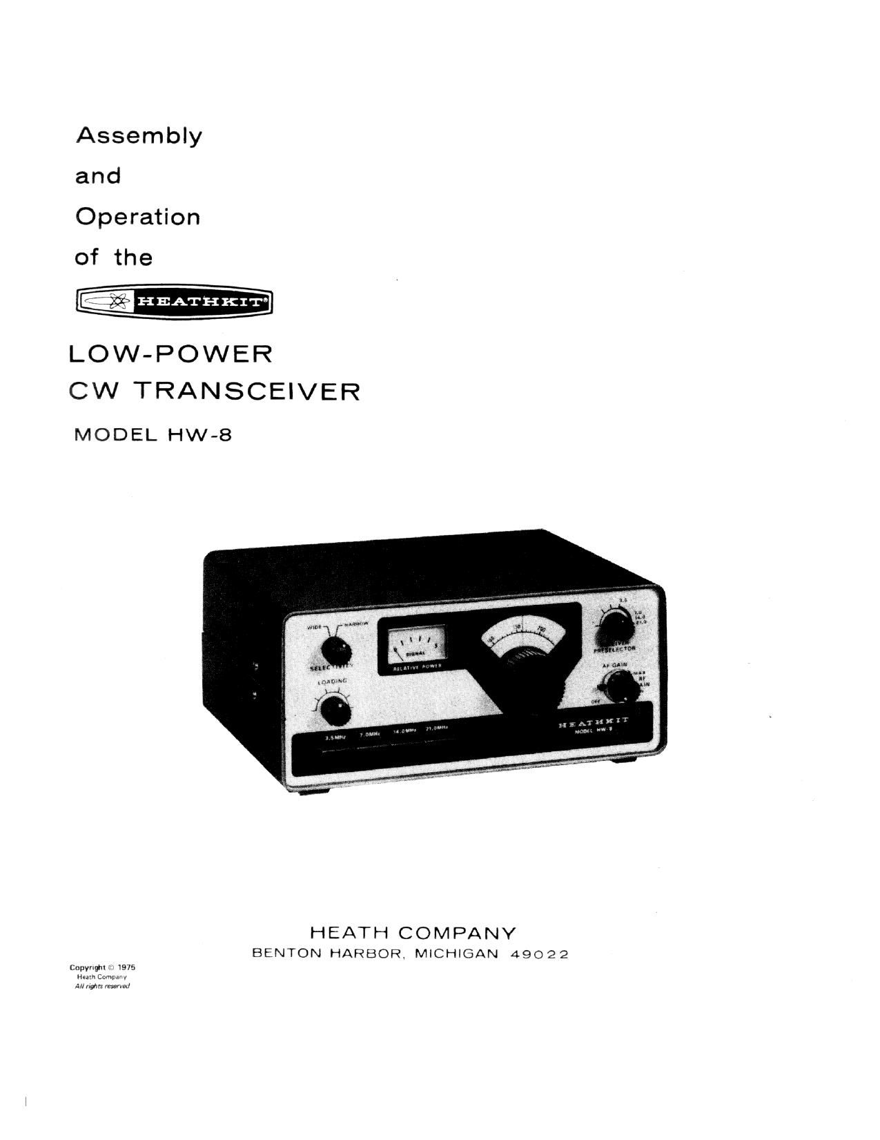
Heathkit HW 8 CW Manual

This is the 29 pages manual for Heathkit HW 8 CW Manual.
Read or download the pdf for free. If you want to contribute, please mail your pdfs to info@audioservicemanuals.com.

Page: 1 / 29
left right
Heathkit HW 8 CW Manual

Extracted text from Heathkit HW 8 CW Manual (Ocr-read)


Page 2

Page 2

TABLE OF CONTENTS

INTRODUCTION .................. 3
ASSEMBLY NOTES ................. 5
Soldering Instructions ................. 6
CIRCUIT BOARD
Parts List ....................... 9
Step»by-Slep Assembly ............... 17
Circuit Board Wiring ................ 37
CHASS IS
Parts List .................. . 43
Step-byStep Assembly ...... 48
Rear Panel Parts Mounting . . ........ 48
Mounting and Wiring Rear Panel ........ 48
Mounting Panel/Circuit Board Assembly . , . . 49
Chassis Parts Mounting and Wiring ....... 50
Front Panel Mounting ............. 54
Installing Knobs ............... 55
Final Parts Mounting and Wiring ........ 56
Preparing Power Cable ............. 57
Preparing Dummy Load ............ 57
INITIAL TESTS .................. 59

ALIGNMENT ................... 61
FINAL ASSEMBLY ................ 65
OPERATION .................... 67

IN CASE OF DIFFICULTY
Visual Checks
Precautions for Bench Testing

Troubleshooting Charts

SPECIFICATIONS ................. 73
CIRCUIT DESCRIPTION .............. 75
CIRCUIT BOARD X-RAY VIEWS .......... 78
CIRCUIT BOARD VOLTAGE CHART ........ 30
IDENTIFICATION CHART ............. 81
SCHEMATIC ................. (Fold-in)
WARRANTY ............. Inside Front Cover

CUSTOMER SERVICE Inside Rear Cover

Page 7

Page 62

VFO (Variable Frequency Oscillator)

i ) Turn the calibrated receiver on and allow it to warm
up. Tune the receiver to approximately 7.0 MHZ.

( l Press the 7.0 MHz pushbutton on the Tramceiver.

( l Connect one end of a suitable length of wire to the
antenna terminal on the calibrated receiver. Loop the
other end of this wire around coil L19/L21 as shown in
inset drawing #2 on Figure 1-2.

( l Turn the Transceiver on and allow it to warm up for at
least 30 minutes before you proceed with the
following adjustments.

NOTE: In the following steps, you will zero beat the
calibrated receiver; first against its own crystal calibrator,
and then against the Transceiver. 'A zero beat is a point
where the two frequencies being combined (or beat against
each other) are exactly the same. As you approach zero
beat, the tone caused by the two combined frequencies will
gradually decrease in pitch and volume until it stops. This
point is very sharp so you must tune very carefully.

l ) Set the calibrated receivers Function switch to the
$88 or CW position.

( i Tune the calibrated receiver to 7.0 MHz. Then turn on
its crystal calibrator and zero beat the receiver
frequency against the crystal calibrator frequency.

( ) Turn off the crystal calibrator. NOTE: Be careful that
you do not change the setting of the receiver
frequency.

( ) Refer to inset drawing #1 of Figure 1-2 and insert the
metal blade (#205-778) into the small end of the
plastic nut starter.

NOTE: Use the alignment tool that you made from the nut
starter and blade for all trimmer adjustments. DO NOT use a
screwdriver.

( ) Turn the Transceiver tuning dial to O.

i ) Adjust trimmer capacitor 63023 until you hear a zero
heat from the calibrated receiver.

HEATHKIT

l l Turn the Transceiver dial to 250.
( ) Turn the calibrated receiver dial to 7.250 MHz.

( l Use the larger alignment tool to turn the slug in coil
L9 until you hear a zero beat from the calibrated
receiver. It may be necessary to turn down the
calibrated receiver's AF gain control.

( l Repeat the VFO alignment steps several times until
tire calibrated receiver's dial coincides with the 0 and
250 marks on the Transceivers dial.

( ) Turn off the calibrated receiver and remove the wire
from around coil Ll9/L21 in the Transceiver. The
calibrated receiver will no longer be used.

MIXER AMPLIFIER
( ) Turn the Transceiver tuning dial to 100.
( ) Connect the RF Probe oi the VTVM to test point

TP2. This is the lead at the indicated end of R49, a
270 S2 (red-violet-brown) resistor.

l 1 Press the 3.5 MHZ pushbutton and adjust coil L13 for
a peak reading on the VTVM.

l ) Press the 7.0 MHz pushbutton and adjust coil L14 for
a peak reading on the VTVM.

( ) Press the 14.0 MHz pushbutton and adjust coil L15
for a peak reading on the VTVM.

l ) Turn the Transceiver tuning dial to 150.
NOTE: When you perform the next step, you may have to

turn the coil slug several turns counterclockwise before you
obtain a peak reading on the VTVM.

( l Press the 21.0 MHz pushbutton and adjust coil L16
for a peak reading on the VTVM.

( ) Disconnect the RF Probe from Test point TP2.